

 English
 русский
 Français
 Español
 عربى
عربى
LQ-RTO Heat-storage high-temperature incineration equipment
Cat:Equipment
Overview Of Tower-Type RTO Regenerative Thermal Oxidizer (RTO) is an organic waste gas treatment equipment that combines high-temperature oxidation wi...
See Details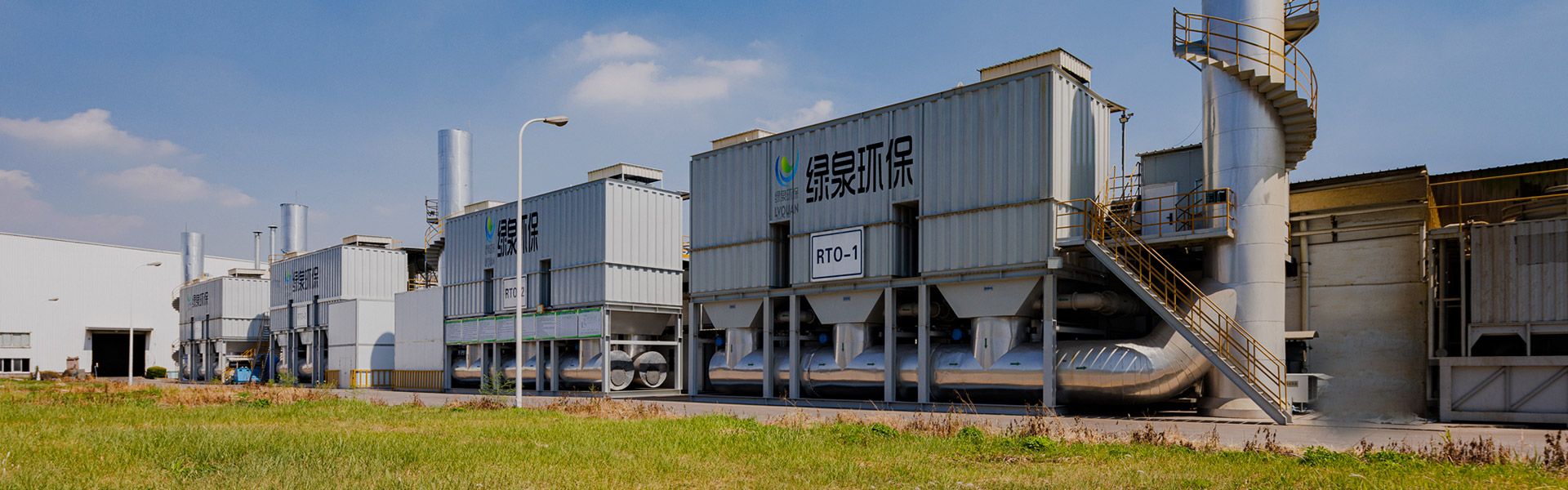
Content
Reliable Organic Waste Gas Treatment Equipment starts at the collection point, not just at the treatment unit itself: how well a hood or duct network captures solvent-laden air before it reaches the treatment stage has as much influence on overall performance as the treatment technology selected afterward. Airflow volume, capture efficiency at the source, and how equipment scale is matched to a facility's actual duct layout together determine whether an organic waste gas purification system performs consistently in daily operation. This article looks at organic waste gas treatment equipment from the collection system outward, covering common equipment types, structural design of the collection and treatment chain, application-specific selection guidance, comparative data across equipment scale tiers, and maintenance practices that keep a system performing as designed over its operating life.
Organic waste gas treatment equipment is the collective term for the collection, ductwork, and process systems that capture solvent-bearing exhaust air generated during coating, printing, chemical processing and similar operations, then treat it before release. Untreated organic waste gas typically contains a mixture of Volatile Organic Compounds, and releasing this air without treatment can contribute to ground-level ozone formation and affect surrounding air quality. Rather than a single machine, organic waste gas treatment equipment usually refers to an engineered chain that begins with hoods or enclosures positioned near the emission source, continues through a header duct network, and ends at a treatment unit that concentrates, destroys or recovers the pollutant load.
A system is only as effective as its weakest link, and in practice that weak link is frequently the collection stage rather than the treatment technology itself. A hood positioned too far from a process station, or a duct network sized without accounting for pressure loss at every branch, can allow a meaningful share of VOC-laden air to escape capture entirely, regardless of how efficient the downstream treatment unit is. This is one reason engineering teams increasingly evaluate organic waste gas treatment equipment as a complete system, from hood design through final stack discharge, rather than focusing evaluation on the treatment unit in isolation.
Facilities considering an upgrade or a new installation generally benefit from mapping every emission point first, recording airflow, VOC concentration, and process operating schedule at each one, before narrowing down equipment type. This mapping exercise also identifies which collection points can reasonably be combined into a shared duct header and which need dedicated treatment due to differing solvent composition or operating timing.
Collection efficiency at the hood and duct level often determines overall system performance as much as the treatment technology itself, which is why organic waste gas treatment equipment is best evaluated as a complete chain rather than a single unit.
The treatment stage of an organic waste gas system generally falls into one of several equipment families, each suited to a particular combination of airflow and concentration. The table below outlines these common types along with the collection approach they are usually paired with in practice.
| Equipment Type | Treatment Approach | Typical Collection Pairing |
|---|---|---|
| Regenerative Thermal Oxidation Systems | High-temperature oxidation of the collected VOC stream | Enclosing hoods or full-booth ventilation for high-capture applications |
| Activated Carbon Adsorption and Concentration Units | Captures VOC molecules onto media, then desorbs and concentrates them for further treatment | Large-volume general ventilation from spray booths and open workshops |
| Biological Treatment Units | Microbial breakdown of VOC and odorous compounds in a media bed | Receiving hoods over process vessels with steady, moderate airflow |
| Condensation and Solvent Recovery Units | Cools the concentrated stream so solvent vapor condenses back to liquid for reuse | Sealed or near-sealed enclosures around high-concentration process equipment |
| Combined Concentration and Oxidation Systems | Pairs an adsorption or rotor concentration stage with a downstream oxidizer | Multiple hoods or booths feeding a shared header duct across a production line |
The choice between these types is rarely made on treatment technology alone; the collection method feeding the equipment shapes which treatment type makes practical sense. A production line served by several partial-enclosure hoods, for example, generally produces a larger volume of more dilute exhaust air than a fully sealed booth, which points toward an adsorption-concentration front end rather than a technology designed for smaller, higher-concentration streams. Organic waste gas treatment equipment suppliers typically ask for hood layout and duct routing information alongside VOC concentration data for exactly this reason.
The collection method in use at a facility often narrows the practical treatment equipment options before concentration data alone would suggest, making hood and duct layout a starting point for equipment selection rather than an afterthought.
Before exhaust air reaches any treatment unit, it passes through a collection system built around hoods, a header duct network, and an induced draft blower that pulls air through the entire chain. Hood types generally fall into three categories: enclosing hoods that surround the emission source almost completely, receiving hoods that capture air rising or moving naturally from a process, and exterior or capturing hoods positioned near but not around an open process station. Each hood type is connected through branch ducts into a main header, which is sized to maintain adequate duct velocity at every point so that captured VOCs remain entrained in the airstream rather than settling out. The induced draft blower, positioned either before or after the treatment unit depending on the system design, provides the pressure needed to move air through hoods, ducts, filters and the treatment stage itself, with the entire chain finally discharging through an elevated exhaust stack.
The illustration below shows a simplified collection-to-treatment layout, numbered to correspond with the description above. This type of layout, with two or more collection points feeding a shared header duct into a single primary treatment unit, is common where several process stations generate similar solvent types and can reasonably share treatment capacity.
Duct velocity and hood placement determine how much of the generated VOC load actually reaches the treatment unit, making collection system design a core part of organic waste gas treatment equipment engineering rather than a secondary detail.
Different organic waste gas treatment equipment configurations place different relative emphasis on pre-filtration, concentration and destruction or recovery, depending on the technology mix selected. Understanding this relative emphasis helps explain why two systems handling similar airflow can have noticeably different vessel sizing and layout. The figures below are illustrative relative process emphasis rather than measured percentages from a specific installation, intended to show the general pattern rather than an exact specification. A compact adsorption-only unit, for instance, devotes most of its internal volume to the concentration stage, while a standard oxidation line devotes the largest share to the destruction stage itself. Combined systems sit between these two patterns, balancing concentration and destruction more evenly. The stacked column chart below places four common configurations side by side to make this relative emphasis easier to compare.
Reading the chart left to right, the compact adsorption unit shows the largest concentration segment, consistent with its role as a front-end capture and concentration technology rather than a final destruction stage on its own. The standard oxidation line shows the reverse pattern, with destruction occupying the largest share, since this configuration is typically applied to exhaust streams that arrive already at a workable concentration for direct oxidation. The combined system and the heavy-duty multi-stage configuration both show a more balanced split between concentration and destruction, reflecting their role in handling larger, more variable exhaust profiles that benefit from both a capture stage and a destruction stage working together. Pre-filtration occupies a comparatively small and fairly consistent share across all four configurations, which makes sense given that its function, protecting downstream media and equipment from particulates, does not scale as directly with airflow or concentration as the other two stages do. This pattern is useful during early project planning, since it gives a rough sense of how vessel sizing and internal layout will differ between configurations even before detailed engineering begins. Facilities comparing quotations from different organic waste gas treatment equipment manufacturers can use this kind of breakdown as a sanity check, asking whether the proposed vessel sizing is broadly consistent with the process stage emphasis that configuration would be expected to have.
Vessel sizing and internal layout differ meaningfully between equipment configurations because each one places different relative emphasis on pre-filtration, concentration and destruction stages.
Industries generate organic waste gas under very different conditions, and the table below sets out common application scenarios alongside the collection and selection considerations most relevant to each.
Industry Scenarios
|
Selection Considerations
|
Textile and furniture applications often present a distinct challenge because ventilation volume can be large relative to the actual VOC load, favoring a concentration stage ahead of destruction to avoid oversizing the oxidizer for mostly clean air. Pharmaceutical and fine chemical applications, by contrast, more frequently call for tighter enclosure and more precise airflow control at the hood level, since batch processes can generate short bursts of higher concentration that a loosely fitted hood would not reliably capture. Matching equipment scale and collection design to these patterns, rather than applying a single standard configuration across every application, is generally what separates a system that performs consistently from one that requires frequent adjustment after commissioning.
Matching hood design and equipment scale to the specific operating pattern of an industry, rather than applying one standard configuration everywhere, is central to consistent organic waste gas treatment equipment performance.
Organic waste gas treatment equipment is generally offered across a range of scale tiers so that vessel sizing can be matched to a facility's actual airflow rather than forcing a choice between a single fixed capacity or significant oversizing. Understanding roughly how airflow handling capacity scales across these tiers helps facilities anticipate footprint and ductwork requirements early in project planning, before detailed engineering drawings are available. The figures below are illustrative reference ranges intended to show the general scaling pattern across common module sizes rather than exact specifications for any single product. Smaller modules are typically suited to a single process line or a small workshop, while larger modules are engineered for multi-line facilities with substantial combined ventilation volume. The area chart below traces this illustrative capacity progression across five common scale tiers.
The shaded area under the curve widens noticeably between the standard and large tiers, illustrating that airflow handling capacity does not increase in a simple straight line as equipment scale grows; the jump from a standard to a large module typically represents a much bigger capacity step than the jump from small to compact. This pattern reflects how modular treatment systems are usually designed, with smaller tiers built around a single vessel and larger tiers built by adding parallel processing trains rather than simply enlarging one vessel indefinitely. For a facility planning a phased expansion, this means jumping from a compact to a standard module may cover several years of growth, while a further jump to a large or heavy-duty tier is generally reserved for a substantial increase in production lines or a facility-wide consolidation of multiple existing systems. The flattening or steepening of the curve at different points also has practical implications for footprint planning, since a heavy-duty tier module generally requires meaningfully more installation space and structural support than the capacity figure alone might suggest. When comparing quotations across equipment scale tiers from different organic waste gas treatment equipment suppliers, it is useful to ask for the actual footprint and structural load figures for the specific tier under consideration, rather than assuming these scale in direct proportion to airflow capacity.
Airflow handling capacity generally increases in larger steps at higher equipment scale tiers, which is a useful consideration when planning a phased facility expansion around organic waste gas treatment equipment.
Footprint is frequently the constraint that determines whether a given organic waste gas treatment equipment technology is workable at a particular site, and the relationship between airflow volume and footprint is not identical across technologies. Some technologies scale more efficiently in footprint terms as airflow increases, while others require proportionally more floor or roof area at higher airflow levels. The scatter plot below places illustrative data points for three common technologies, regenerative thermal oxidation, activated carbon adsorption and biological treatment, across a range of airflow volumes, to show how footprint tends to spread out differently for each. Each point represents an illustrative reference configuration rather than a specific measured installation, intended to demonstrate the general pattern engineers typically observe when comparing proposals across technology types.
The activated carbon adsorption points sit consistently below the other two technologies across the airflow range shown, indicating a comparatively smaller footprint for a given airflow, which aligns with the compact, modular nature of adsorption vessels and rotor concentration units. The regenerative thermal oxidation points sit in the middle of the spread, reflecting the additional vessel volume needed for combustion chambers and ceramic heat exchange media, though the footprint still scales in a fairly predictable, gradual pattern as airflow increases. The biological treatment points climb the steepest of the three, showing that footprint grows more quickly with airflow for media-bed biological systems, largely because biofiltration relies on sufficient media bed surface area and residence time rather than a compact reaction vessel. This steeper slope is one reason biological treatment tends to be favored more often at facilities with more available land area, such as certain food processing or wastewater-adjacent sites, and less often at urban or multi-story facilities where roof space is limited. None of these three trend lines implies that one technology is categorically superior, since footprint is only one of several selection factors alongside energy use, solvent compatibility and maintenance needs discussed elsewhere in this guide. For facilities with a defined footprint ceiling, however, this kind of comparison is a useful early screening tool before requesting detailed vessel drawings from a prospective organic waste gas treatment equipment manufacturer.
Footprint scales differently with airflow across treatment technologies, with adsorption-based systems generally showing the most compact footprint growth and biological treatment the steepest, making footprint a practical early screening factor at space-constrained sites.
Capture efficiency at the hood, meaning the share of generated VOC-laden air that is actually pulled into the collection system rather than escaping into the surrounding workshop, is a distinct metric from the removal efficiency of the treatment unit discussed elsewhere in this guide, and both matter for overall system performance. Different hood types are associated with different typical capture efficiency ranges based on how closely they surround or follow the emission source. Enclosing hoods, which surround a process almost completely, are generally associated with the highest capture efficiency because there is little opportunity for the exhaust to escape before entering the duct. Receiving hoods, positioned to intercept air already moving upward or outward from a process, sit in a middle range, while exterior or capturing hoods, which draw air toward them from an open station without any enclosure, generally show the widest variability and the lowest typical capture efficiency of the three. The gauge-style illustration below presents these three hood types side by side using illustrative typical midpoint values.
The enclosing hood ring shows the fullest arc of the three, consistent with its position as the collection method generally associated with the highest typical capture efficiency, since the near-complete surround limits how much exhaust can dissipate before entering the duct. The receiving hood arc sits at a noticeably lower fill level, reflecting its reliance on the natural rise or movement of the exhaust plume, which introduces more variability depending on room air currents and hood placement distance. The exterior hood arc is the smallest of the three, illustrating why this hood type is generally reserved for situations where full or partial enclosure is not practical, such as large open process stations, and why designers often compensate with increased airflow volume when this hood type is unavoidable. These typical ranges are a useful starting reference during early design, but actual capture efficiency at a specific site depends heavily on cross-drafts, hood distance from the source, and how consistently operators maintain hood positioning during the process. Facilities with a choice between hood types for a given application generally find that investing in tighter enclosure, where the process allows it, reduces the burden placed on downstream treatment equipment to compensate for lost capture, which in turn can support more consistent overall emission performance. This is one reason organic waste gas treatment equipment proposals increasingly include hood design recommendations alongside the treatment unit specification itself, rather than treating hood selection as a detail left entirely to the facility's own ventilation contractor.
Enclosing hoods generally achieve the highest typical capture efficiency, followed by receiving hoods and then exterior hoods, making hood type selection a meaningful lever for overall organic waste gas treatment equipment performance.
Because collection performance and treatment performance are interdependent, maintenance for organic waste gas treatment equipment needs to cover the full chain rather than the treatment unit alone. The cards below summarize maintenance focus areas across the collection and treatment chain.
Hood Positioning and ConditionCheck hood distance and alignment relative to the process source periodically, since drift in positioning over time can quietly reduce capture efficiency even when the rest of the system appears to be operating normally.Duct Integrity and SealingInspect duct joints, flexible connections and access panels for leaks, since even small duct leaks can reduce the airflow reaching the treatment unit and lower overall system pressure.Blower and Motor ConditionMonitor blower vibration, bearing temperature and belt tension, and confirm fan speed is still delivering the design airflow, since gradual mechanical wear can reduce system airflow well before a failure occurs.Treatment Media and ChamberFollow the media inspection and replacement schedule appropriate to the treatment technology in use, and track temperature and pressure drop trends inside the treatment chamber over time.Instrumentation and ControlsVerify sensor calibration for temperature, pressure and flow readings on a regular schedule, since drifted sensor readings can mask a developing performance issue elsewhere in the system.
A practical approach many facilities adopt is to schedule a combined inspection walk that checks hood positioning, duct condition and treatment unit readings in a single visit, since these three areas influence one another and reviewing them together makes it easier to trace the root cause when a performance metric starts to drift. Keeping documentation of duct layout and hood specifications on hand also speeds up future maintenance and any facility changes, since it allows a technician or supplier to quickly reference the original design intent rather than re-surveying the entire system each time an adjustment is needed.
Maintenance for organic waste gas treatment equipment is most effective when it covers hoods, ductwork, blower and treatment media together, since a decline in any one area can affect overall system performance regardless of how well the other areas are maintained.
A number of trends are shaping how organic waste gas treatment equipment is designed today, particularly on the collection side of the system. Hood and duct design is increasingly engineered alongside the treatment unit rather than specified separately, reflecting a broader recognition that collection efficiency is not a fixed given but a design variable that can be improved. Modular, tiered equipment scaling, discussed earlier in this guide, is also becoming more common, allowing facilities to expand treatment capacity in defined steps as production grows rather than committing to a single large system upfront. Alongside this, remote monitoring of duct pressure, blower performance and treatment chamber conditions is being incorporated more frequently into control systems, giving maintenance teams earlier visibility into gradual performance drift across the collection and treatment chain.
Manufacturing depth and in-house fabrication capability remain important considerations when evaluating an organic waste gas treatment equipment supplier, since collection ductwork, hoods and treatment vessels are typically project-specific and benefit from close coordination between design engineering and the fabrication shop. Lvquan Environmental Protection Engineering Technology Co., Ltd., based in Gaoyou, within Yangzhou in Jiangsu province, is a joint-stock enterprise formed by a team with more than 30 years of combined experience in VOCs equipment design and manufacturing. Operating as a dedicated manufacturer of organic waste gas treatment engineering equipment, the company maintains a registered capital of 22 million yuan, fixed assets of close to 40 million yuan, and total assets of nearly 60 million yuan, all supported by a 9,800 square meter production facility. With more than 200 sets of machining equipment on site and a team of 120 employees, the company operates with an annual production capacity valued at 100 million yuan, capabilities that support the kind of project-specific hood, duct and vessel fabrication that organic waste gas treatment equipment installations generally require.
For facilities planning a new installation or an upgrade, it is generally worth asking a prospective organic waste gas treatment equipment manufacturer or wholesaler how collection system design is handled within their scope of work, since a supplier that treats hood and duct engineering as part of the same project as the treatment unit is better positioned to deliver a system that performs as intended once installed.
Collection-side design, modular scaling and remote monitoring are among the clearer trends in current organic waste gas treatment equipment, alongside continued attention to in-house manufacturing depth among suppliers in this space.
Q1. What is the difference between collection efficiency and treatment efficiency?Collection efficiency describes how much of the generated VOC-laden air is actually pulled into the hood and duct system, while treatment efficiency describes how much of that collected air is successfully treated once it reaches the treatment unit; both need to be reasonably high for overall emission performance to be consistent. |
Q2. How is the right equipment scale tier chosen for a facility?Scale selection generally starts with measuring current and reasonably anticipated future airflow across all collection points, then matching that combined figure against the capacity range of available equipment tiers, with some facilities choosing a modular approach that allows capacity to be added in steps. |
|
Multiple hoods can often share a common header duct and treatment unit when the solvent composition and operating schedule across the connected process stations are broadly compatible, though duct sizing needs to account for the combined airflow and maintain adequate velocity from every branch. |
Q4. What is the most common cause of reduced performance in an existing system?Gradual issues such as hood position drift, duct leaks, or media approaching the end of its effective service life are common causes of reduced performance, which is why maintenance programs that track pressure, temperature and airflow trends over time tend to catch problems earlier than inspections that only check equipment when an issue is already apparent. |
Q5. Can an existing collection system be upgraded without replacing the treatment unit?In many cases hood repositioning, duct modifications or additional collection points can be added to an existing system without replacing the treatment unit, provided the treatment unit still has adequate spare capacity to handle the resulting airflow. |
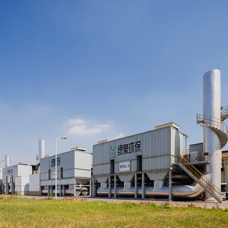
Overview Of Tower-Type RTO Regenerative Thermal Oxidizer (RTO) is an organic waste gas treatment equipment that combines high-temperature oxidation wi...
See Details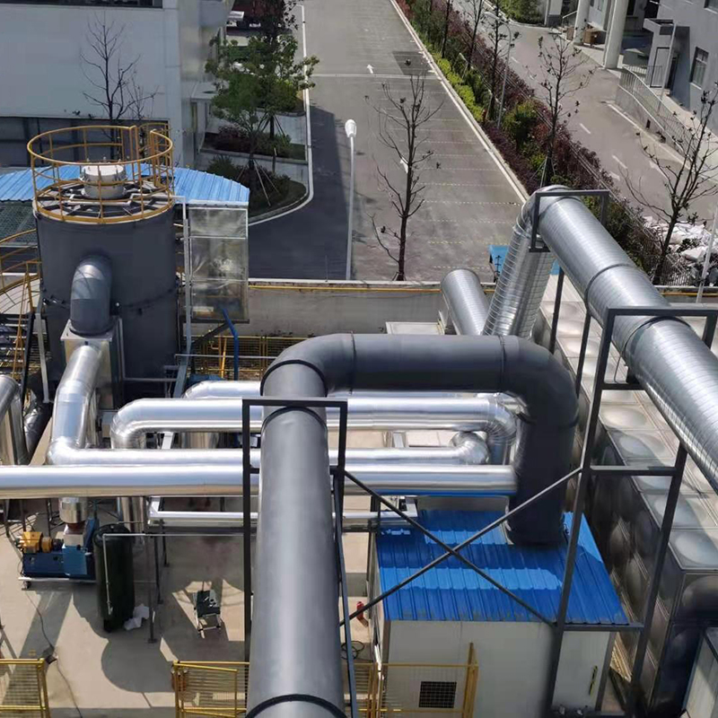
Overview Of Tower-Type RTO Our company offers two types of rotary RTO, which are the rotary RTO and the single barrel multi-valve RTO. The rotary RTO,...
See Details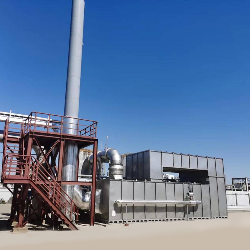
Overview Catalytic combustion is a purification method that uses catalysts to oxidize and decompose combustible substances in exhaust gas at low tempe...
See Details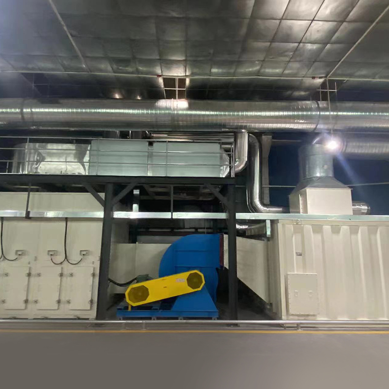
Overview Of Variable Freouency Zeolite Turntable Our company's zeolite concentration turntable uses a combination of zeolite modules, with a high zeol...
See Details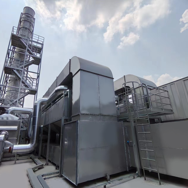
Overview of Activated Carbon Fiber Organic Solvent Purification Recovery Device The Activated Carbon Fiber Organic Solvent Purification Recovery Syste...
See Details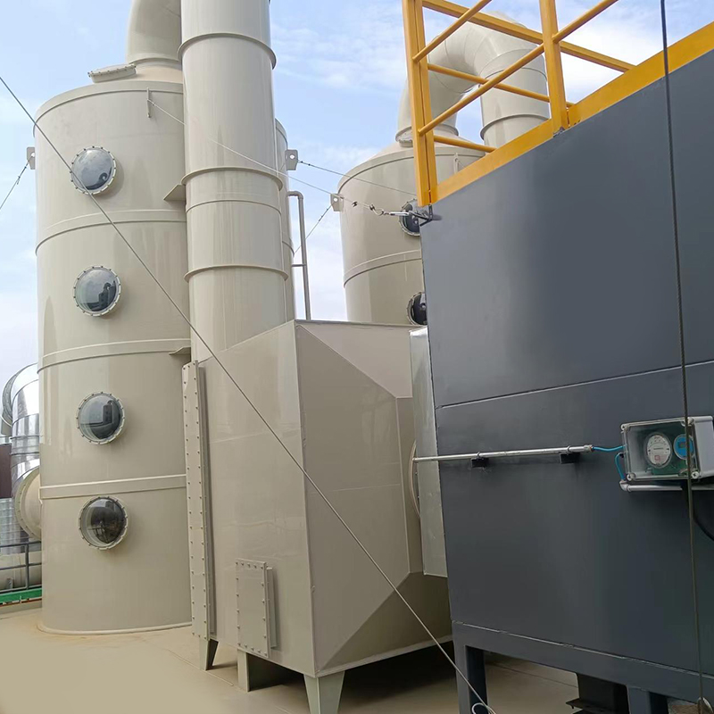
Overview The VOC-ACA series organic gas particle carbon purification and recovery equipment is used for the absorption, recovery, and reuse of organic...
See Details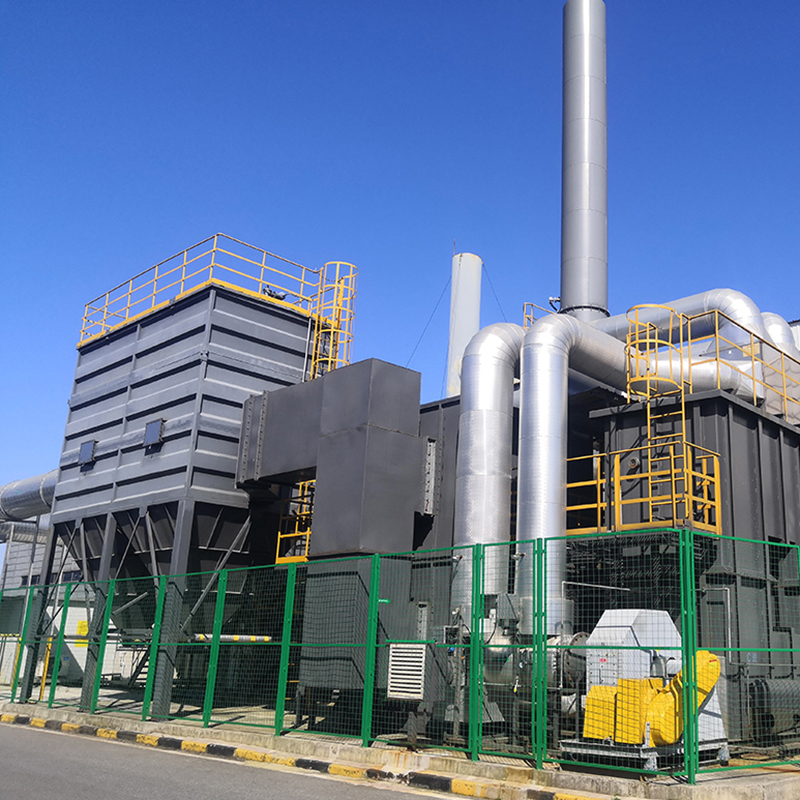
Concept Of Zeolite Wheel+RTO System Using zeolite wheel to adsorb organic waste gas, the low concentration and high air volume waste gas is concentrat...
See Details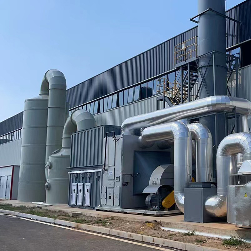
Concept Of Fixed Bed Zeolite + Catalytic Combustion As A Set Of Equipment The fixed bed zeolite + catalytic combustion device is suitable for the conc...
See Details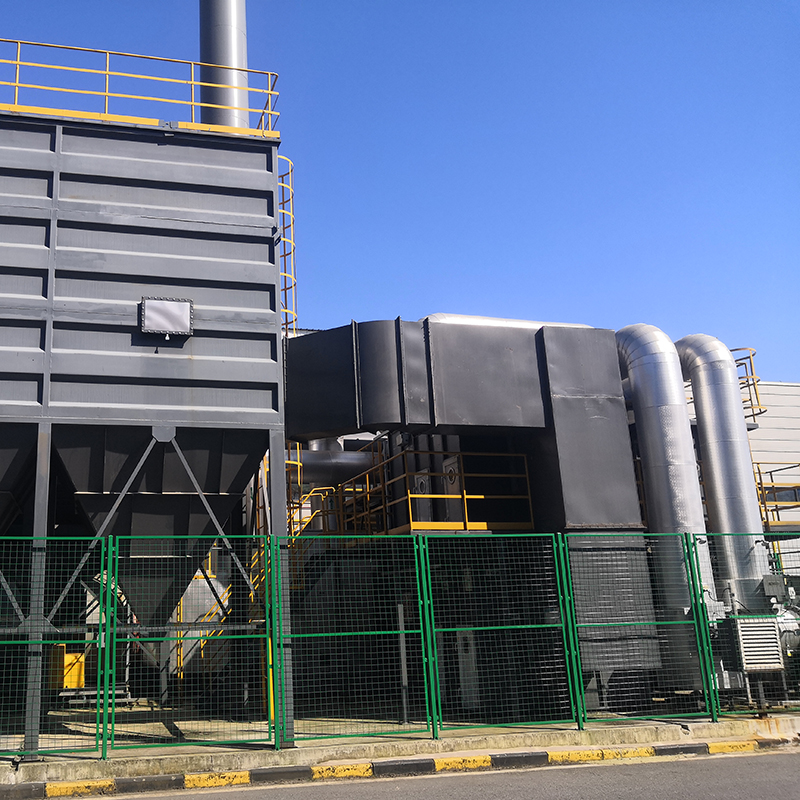
The Concept Of Zeolite Wheel+ Direct Combustion High-Temperature Incineration Equipment The purpose of employing rotary drum zeolite adsorption for or...
See Details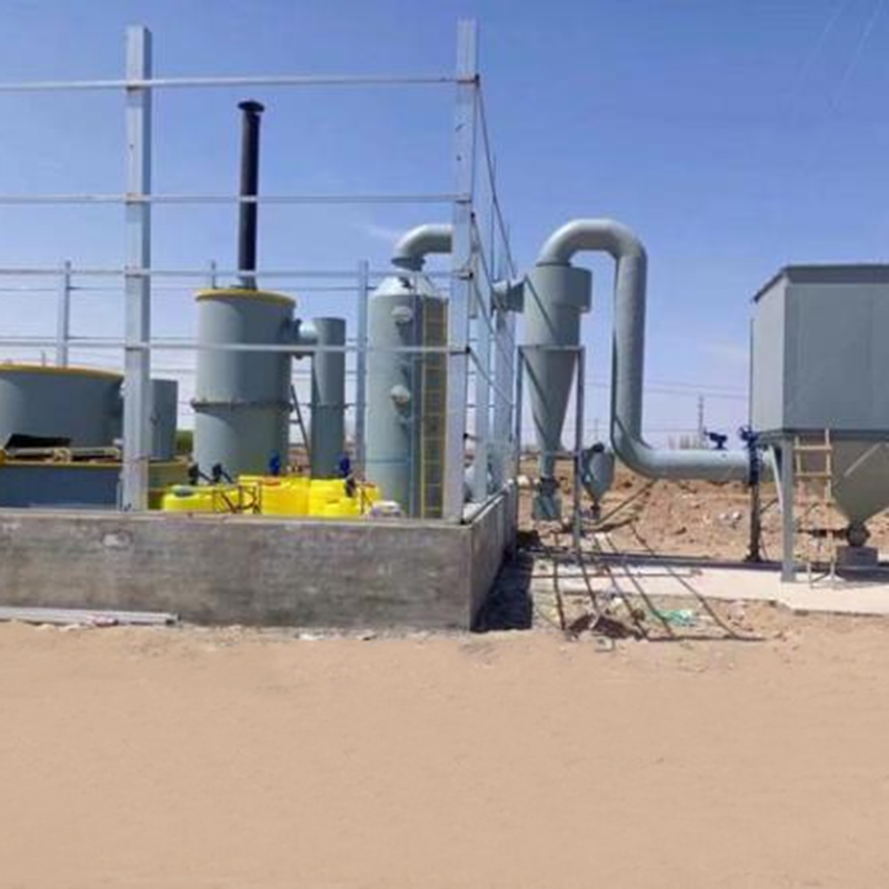
Overview Solid waste incineration furnaces are essential equipment in the management of solid waste, designed to transform waste materials into ash an...
See DetailsMOBILE
Product Manual

Copyright © Lv quan Environmental Protection Engineering Technology Co., Ltd. All Rights Reserved. Vocs Organic Waste Gas Treatment Engineering Equipment Manufacturer

