

 English
 русский
 Français
 Español
 عربى
عربى
LQ-RRTO Rotary heat-storage high-temperature incineration equipment
Cat:Equipment
Overview Of Tower-Type RTO Our company offers two types of rotary RTO, which are the rotary RTO and the single barrel multi-valve RTO. The rotary RTO,...
See Details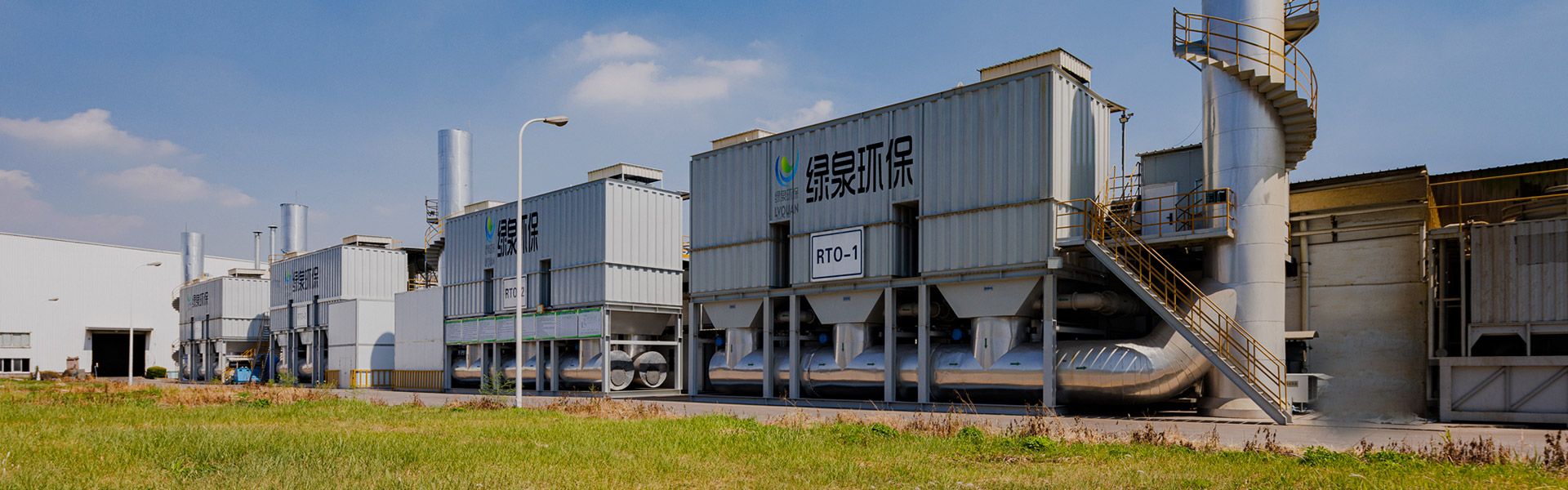
Content
Matching exhaust characteristics to the right technology is the first and most important step when specifying VOCs Organic Waste Gas Treatment Engineering Equipment. Concentration, flow rate and pollutant composition determine whether regenerative thermal oxidation, activated carbon adsorption, biofiltration or a combined multi-stage system is the more workable configuration for a given exhaust stream, and no single equipment type performs equally well across every industrial scenario. This article walks through the common equipment types used in VOCs Organic Waste Gas Treatment, explains how they work, compares their performance characteristics with data visualizations, and outlines selection and maintenance practices that process engineers and procurement teams can apply when evaluating organic waste gas purification systems for coating lines, printing workshops, chemical processing plants, electronics manufacturing and similar emission sources.
Volatile Organic Compounds, commonly abbreviated as VOCs, are carbon-based chemicals that evaporate readily at normal temperatures and are released during processes such as spray coating, printing, degreasing, chemical synthesis and solvent-based cleaning. When these compounds are vented into the atmosphere without treatment, they contribute to ground-level ozone formation and can affect air quality around a production site. VOCs Organic Waste Gas Treatment Engineering Equipment refers to the mechanical and process systems designed to capture, concentrate or destroy these compounds before the exhaust stream leaves the facility.
Modern organic waste gas treatment equipment is engineered around three broad functions: capturing the pollutant-laden air through a collection duct network, concentrating or separating the VOC molecules from the air stream, and either destroying them through oxidation or recovering them through condensation or adsorption-desorption cycles. The equipment selected for a given plant depends heavily on the volume of air to be processed, the concentration of VOCs in that air, the mixture of compounds present, and the operating pattern of the production line, whether continuous or batch.
Because industrial exhaust gas profiles vary so widely between industries, manufacturers of VOCs organic waste gas treatment engineering equipment typically offer several technology platforms rather than a single fixed design, and equipment is usually engineered or configured around the specific duct layout, airflow volume and solvent mixture of the client's production process. This is why waste gas treatment engineering equipment is generally described as a project-based, engineered solution rather than an off-the-shelf appliance.
Airflow volume, VOC concentration and solvent composition are the three variables that determine which VOCs Organic Waste Gas Treatment technology is appropriate for a given exhaust stream, which is why treatment equipment is typically engineered around the specific process rather than sold as a single universal design.
Several equipment families make up the current market for organic waste gas purification systems, each suited to a different combination of flow rate and concentration. The table below summarizes the mainstream types of VOCs Organic Waste Gas Treatment Engineering Equipment along with their general operating principle and the concentration range they are typically matched to in industrial practice.
| Equipment Type | Working Principle | Typical Concentration Range | Common Applications |
|---|---|---|---|
| Regenerative Thermal Oxidizer (RTO) | Heats the exhaust stream to a temperature at which VOC molecules oxidize into carbon dioxide and water, recovering heat through ceramic media beds | Low to medium concentration, high airflow | Printing, coating, packaging |
| Regenerative Catalytic Oxidizer (RCO) | Uses a catalyst bed to lower the oxidation temperature needed to break down VOC molecules, reducing supplementary fuel demand | Low to medium concentration | Electronics, automotive parts coating |
| Activated Carbon Adsorption / Concentration-Desorption | Adsorbs VOC molecules onto activated carbon or zeolite media, then desorbs and concentrates them for further oxidation or recovery | Low concentration, large airflow | Spray booths, large workshop ventilation |
| Biofiltration | Passes exhaust air through a biologically active media bed where microorganisms metabolize VOC molecules | Low concentration, odorous streams | Food processing, wastewater treatment plants |
| Condensation Recovery | Cools the exhaust stream so that VOC vapor condenses back into liquid solvent for recovery and reuse | High concentration, low airflow | Solvent recovery in chemical processing |
| Combined Multi-Stage System | Pairs a concentration stage, such as an adsorption rotor, with a destruction stage, such as an RTO or RCO, to handle large low-concentration airflows efficiently | Wide range, especially large-volume low-concentration streams | Multi-line coating and printing plants |
Adsorption-based concentration technology has become increasingly common as a front-end stage for large-airflow, low-concentration exhaust streams, since it reduces the volume of air that needs to be sent to the oxidizer and lowers the overall energy demand of the system. Combining a concentration stage with a thermal or catalytic destruction stage is one of the more practical configurations for organic waste gas purification when the ventilation volume of a workshop is large but the actual VOC loading is comparatively dilute.
There is no universally superior equipment type; selecting VOCs organic waste gas treatment equipment is a matching exercise between airflow, concentration, solvent composition and the operating schedule of the production process it serves.
A typical combined-process VOCs organic waste gas treatment engineering equipment line follows a consistent structural logic regardless of the specific technology chosen. Exhaust air is first drawn from the production process through a collection duct network, then passed through a pre-filtration stage to remove particulates, oils and mists that would otherwise foul downstream media. The filtered air then enters the concentration or adsorption stage, where VOC molecules are captured onto activated carbon or zeolite media while cleaned air is released or recirculated. Periodically, a smaller volume of hot air is used to desorb the captured VOCs off the media, producing a concentrated stream that is routed to the oxidation chamber. Inside the oxidation chamber, the concentrated stream is heated, with or without a catalyst, to a temperature sufficient to break the VOC molecules down into carbon dioxide and water vapor. Heat exchange elements recover a portion of the thermal energy released during oxidation and use it to preheat incoming air, and the treated gas is finally released through an exhaust stack while a programmable logic controller cabinet manages fan speed, valve switching and temperature setpoints.
The illustration below shows a simplified structural layout of this type of system, numbered to correspond with the main functional sections described above. This kind of layout is representative of the equipment configuration used for many coating and printing exhaust lines, though duct routing, stage count and vessel sizing are adjusted for each project based on airflow and available installation space.
Regardless of the specific technology chosen, VOCs organic waste gas treatment engineering equipment generally follows a collect, concentrate, destroy and monitor structure, with duct sizing and vessel capacity engineered around the specific airflow of the connected process.
Removal efficiency is one of the first performance indicators engineers look at when comparing organic waste gas purification technologies, and it varies meaningfully between equipment types. The figures below represent commonly cited midpoint values from general engineering practice rather than results from a single specific test, and actual performance for any installation depends on the exhaust concentration, air-to-media contact time and maintenance condition of the equipment. Combined multi-stage systems and regenerative thermal oxidizers are generally associated with the higher end of the removal efficiency range because they pair concentration with high-temperature destruction. Biofiltration and condensation recovery tend to sit at a comparatively lower or more variable point on this scale, largely because their effectiveness depends heavily on the specific solvent mixture being treated. The horizontal bar chart below places six common equipment types side by side so the relative pattern is easier to read at a glance.
Reading the chart from top to bottom, combined multi-stage systems and regenerative thermal oxidizers sit at the upper end of the range because the oxidation step destroys VOC molecules outright rather than transferring them between phases. Regenerative catalytic oxidizers perform close behind, since the catalyst allows a lower reaction temperature while still achieving thorough breakdown of most common solvents. Activated carbon adsorption performs well for a wide range of compounds but can show reduced capture of very light, low-molecular-weight VOCs that pass through the media more readily. Biofiltration efficiency is more sensitive to the biodegradability of the specific solvent mixture, and performance can vary across a broader band depending on VOC type, humidity and media condition. Condensation recovery is generally reserved for higher-concentration streams, and its apparent efficiency figure reflects performance in that concentration range rather than dilute ventilation air. None of these numbers should be read as a fixed guarantee for a specific site, since actual performance depends on inlet concentration, contact time, temperature control and how consistently the equipment is maintained. For process engineers, the practical takeaway is that a single technology rarely covers every part of a facility's emission profile, which is why combined multi-stage VOCs Organic Waste Gas Treatment Engineering Equipment has become a common configuration for facilities with several exhaust points of differing concentration. Procurement teams evaluating a VOCs organic waste gas treatment equipment supplier should ask how the quoted efficiency figure was derived and under what concentration and airflow assumptions it applies, since efficiency claims that omit these conditions are difficult to compare across manufacturers.
Removal efficiency figures are only meaningful when read alongside the concentration and airflow conditions they were measured under, which is why equipment selection should be based on a site-specific exhaust profile rather than a single published percentage.
Different industries generate exhaust streams with distinct concentration, flow rate and solvent composition profiles, and matching equipment to the application is central to reliable operation of VOCs Organic Waste Gas Treatment Engineering Equipment. The table below sets out common application scenarios alongside the equipment types typically applied to them, followed by the main criteria engineers weigh when narrowing the shortlist for a project.
Typical Application Scenarios
|
Key Selection Criteria
|
Airflow volume and installation footprint often become the deciding factors once a technology family has been narrowed down, since compact activated carbon or rotor concentration units are frequently favored for facilities with limited rooftop space, while larger regenerative thermal oxidation systems are more common where floor space is available and airflow volumes are substantial. For facilities running multiple production lines with different solvent profiles, a segmented approach is common, in which smaller, more concentrated streams are routed to a dedicated recovery or oxidation unit while larger, low-concentration ventilation air is handled by a separate adsorption-concentration train. This kind of layered configuration allows a VOCs organic waste gas treatment engineering equipment package to be sized more efficiently than a single oversized unit designed to handle the combined peak load of every emission point at once.
Segmenting exhaust streams by concentration and airflow before selecting equipment generally results in a more efficiently sized VOCs organic waste gas treatment engineering equipment package than routing every collection point into a single oversized system.
Energy consumption in thermal-oxidation-based VOCs organic waste gas treatment equipment is closely tied to inlet VOC concentration, and this relationship is worth understanding before specifying supplementary fuel or heater capacity. As the concentration of VOCs entering the oxidation chamber increases, the heat released by the oxidation reaction itself contributes a larger share of the energy needed to sustain the process temperature, reducing the amount of supplementary fuel or electric heating the system requires. At sufficiently high concentration, a regenerative thermal oxidizer can approach what engineers describe as autothermal operation, where the heat released by oxidizing the VOCs is enough to sustain the reaction temperature with little to no ongoing supplementary energy input. The line chart below illustrates this general downward trend using a relative energy consumption index rather than absolute energy figures, since actual values depend on the heat exchanger efficiency, insulation quality and specific solvent mixture of a given installation.
The curve slopes downward steadily rather than dropping in a straight line, which reflects the fact that each additional increment of VOC concentration contributes proportionally more oxidation heat as the total load increases. At the lower end of the concentration range shown, supplementary energy input is at its highest because the oxidation reaction alone does not release enough heat to sustain the required temperature, so a heater or burner must make up the difference. As concentration rises through the middle of the range, the relative energy index falls fairly quickly, showing that even a moderate increase in VOC loading can meaningfully reduce supplementary fuel demand. Near the right side of the chart, the curve flattens out at a low value, consistent with the system approaching autothermal operation, where oxidation heat alone is close to sufficient. Many regenerative thermal oxidizers begin to approach this autothermal range somewhere around 1,200 to 1,500 mg per cubic meter, though the exact threshold depends on the heating value of the specific solvents present in the exhaust stream. This pattern is one reason engineers sometimes design a concentration stage ahead of the oxidizer for dilute, high-volume exhaust: raising the concentration of the stream that actually reaches the oxidation chamber can shift operation further along this curve and reduce ongoing supplementary energy demand. For facilities evaluating VOCs organic waste gas treatment engineering equipment suppliers, it is reasonable to ask how a proposed system is expected to perform across the actual concentration range measured at the plant, rather than relying on a single reference point.
Supplementary energy demand in thermal VOCs treatment systems generally falls as inlet concentration rises, which is a key reason concentration stages are frequently paired with oxidation equipment for dilute, high-volume exhaust streams.
Beyond removal efficiency and energy consumption, several other factors distinguish one VOCs organic waste gas treatment technology from another in day-to-day operation. The table below expands the comparison to cover footprint, noise level, byproduct handling and suitability for streams containing particulates, giving a broader reference point for shortlisting equipment types before requesting a detailed engineering proposal.
| Characteristic | RTO | Activated Carbon Adsorption | Biofiltration |
|---|---|---|---|
| Relative footprint | Larger | Compact | Larger |
| Sensitivity to particulates | Moderate, pre-filtration recommended | High, pre-filtration essential | Moderate |
| Byproduct handling | Minimal, mainly heat and treated flue gas | Spent media replacement over time | Periodic media bed renewal |
| Best-fit concentration | Low to medium, higher favors autothermal | Low | Low |
| Response to variable solvent mixtures | Broadly tolerant | Depends on compound polarity | Depends on biodegradability |
Regenerative thermal oxidation stands out for its broad tolerance of different solvent mixtures, which makes it a common choice at facilities that run varied production schedules across several product lines. Activated carbon adsorption performs well for consistent, well-characterized VOC streams but requires more rigorous pre-filtration to protect the media from fouling. Biofiltration tends to fit best where the specific compounds present are known to biodegrade efficiently, and it is comparatively less suited to fast-changing or highly variable solvent mixtures.
No single performance metric captures the full picture of how a VOCs organic waste gas treatment technology behaves in real operation, which is why engineers often weigh several dimensions side by side rather than ranking equipment on removal efficiency alone. The radar chart below rates three common technologies, regenerative thermal oxidation, activated carbon adsorption and biofiltration, across five practical dimensions using an illustrative one-to-five relative scale rather than a precise measured score. Reading a radar chart is straightforward: the further a line extends toward the outer edge on a given axis, the stronger that technology tends to perform on that particular dimension relative to the others shown. A technology that forms a larger overall shape is not automatically the better overall choice, since the dimensions that matter most will differ depending on the site.
The regenerative thermal oxidation line extends furthest on the removal efficiency axis, consistent with its position at the higher end of the bar chart shown earlier in this article, but it sits closer to the center on footprint compactness, reflecting the larger vessel and ductwork typically required for high-temperature oxidation and heat recovery. Activated carbon adsorption shows a more balanced shape overall, extending reasonably far on efficiency, energy efficiency and footprint compactness at once, which explains why it is frequently selected as a front-end concentration stage even when a separate technology handles final destruction. Biofiltration extends furthest on energy efficiency and maintenance simplicity, since biological media beds generally consume comparatively little electrical energy and do not require frequent replacement, but it pulls in noticeably on concentration range adaptability, reflecting its narrower operating window compared with combustion-based technologies. None of the three shapes dominates every axis, which is the core reason multi-stage combinations exist: pairing a technology strong in energy efficiency and footprint with one strong in destruction efficiency and concentration tolerance often produces a more balanced overall system than relying on a single technology alone. When comparing shortlisted equipment against this kind of chart, it is worth asking a prospective VOCs organic waste gas treatment engineering equipment supplier to explain which of these five dimensions their proposed configuration was specifically optimized around, since a system tuned for footprint compactness will typically involve different design trade-offs than one tuned purely for removal efficiency.
No single technology scores highest across every performance dimension, which is the practical reasoning behind combined multi-stage VOCs organic waste gas treatment engineering equipment.
Selecting VOCs organic waste gas treatment engineering equipment is rarely reduced to a single number, and experienced process engineers generally weigh several categories of information before settling on a configuration. The donut chart below illustrates a commonly used rule-of-thumb weighting across five broad categories of consideration; it is intended as a general planning guide rather than a fixed formula, and the actual weighting will shift depending on the regulatory context, site constraints and production schedule of a particular facility. VOC concentration and composition typically carries the largest share of attention early in a project because it determines which technology families are even feasible, while exhaust air flow rate shapes vessel and duct sizing once a technology family has been chosen. Space and installation constraints, emission standard requirements and process compatibility round out the remaining considerations, and each can shift the final decision even after concentration and airflow point toward a particular technology.
VOC concentration and composition occupies the largest single segment of the chart because it directly determines which technology families are technically workable before any other factor is even considered; a stream that is too dilute for efficient condensation recovery, for example, is generally directed toward adsorption or oxidation instead regardless of other preferences. Exhaust air flow rate and emission standard requirements are weighted similarly to one another, since airflow drives the physical sizing of the equipment while target emission levels influence how many treatment stages are needed to reach a satisfactory outcome. Space and installation constraints and process compatibility make up smaller but still meaningful shares, and either one can become the deciding factor at a site where rooftop space is limited or where a production line cannot tolerate the ductwork routing a particular technology would require. This weighting is best used as a starting checklist rather than a scoring formula: a facility with unusually tight space constraints, for instance, may reasonably give that category more influence than the general planning guide suggests. Engineers reviewing proposals from a VOCs organic waste gas treatment engineering equipment manufacturer or supplier often find it useful to walk through each of these five categories explicitly and confirm that the proposed configuration addresses all of them, rather than focusing on a single headline performance figure.
Concentration and composition of the exhaust stream generally carries the most weight in early-stage equipment selection, with airflow, space, emission targets and process compatibility shaping the final configuration.
Routine maintenance has a direct bearing on how consistently VOCs organic waste gas treatment engineering equipment performs over its service life, and different components of the system call for different maintenance intervals and checks. The cards below summarize maintenance focus areas across the main functional sections of a typical combined-process system, from pre-filtration through the control cabinet.
Pre-Filtration SectionInspect and replace filter media on a regular schedule to prevent particulate carryover into the adsorption or oxidation stage, and check for pressure drop increases across the filter bank.Adsorption / Concentration MediaMonitor adsorption capacity over time, check desorption fan and valve cycling, and schedule media inspection or replacement once capture performance begins to decline.Oxidation ChamberCheck burner or catalyst condition, verify temperature sensor calibration, and inspect ceramic heat exchange media for channeling or breakdown that could reduce heat recovery.Fans and DuctworkInspect fan bearings and belts, check duct joints for leaks, and confirm damper positioning matches the intended airflow routing for each operating mode.PLC Control CabinetReview alarm history, confirm sensor readings against manual measurements periodically, and keep firmware and control logic documentation current for operator reference.
Beyond component-level checks, keeping a maintenance log that tracks pressure drop, temperature trends and desorption cycle frequency over time gives operations staff an early warning of gradual performance drift before it becomes a larger issue. Facilities that operate multiple production shifts often find it useful to schedule filter and media inspections during planned production downtime, which minimizes disruption while still keeping the VOCs organic waste gas treatment engineering equipment in good working condition. Working with a manufacturer or supplier that can provide spare parts and technical support for the specific equipment configuration installed is also a practical consideration when planning long-term operation and maintenance budgets.
Tracking pressure drop, temperature and cycle frequency over time is one of the more practical ways operations teams catch gradual performance drift in VOCs organic waste gas treatment equipment before it affects overall system output.
Several broader trends are shaping how VOCs organic waste gas treatment engineering equipment is designed and specified today. Combined multi-stage configurations, pairing a concentration stage with a destruction stage, continue to gain ground over single-technology systems because they generally allow better matching between a facility's actual exhaust profile and the equipment sizing, particularly for large-airflow, low-concentration ventilation streams. Digital monitoring and remote data logging are also becoming more common additions to control cabinets, giving operations teams visibility into temperature trends, fan status and desorption cycles without requiring constant on-site checks. Heat recovery design continues to improve as well, with more attention paid to how thermal energy released during oxidation can be reused elsewhere in a facility's process, rather than simply exhausted through the stack.
Manufacturing capability and engineering depth matter when evaluating a VOCs organic waste gas treatment engineering equipment supplier, since project-based systems require accurate fabrication, reliable component sourcing and the ability to adapt a design to a client's existing duct layout and available space. Lvquan Environmental Protection Engineering Technology Co., Ltd. is located in Gaoyou, in the city of Yangzhou, an area often referred to as the north gate of Jiangsu province. The company is a joint-stock enterprise formed through cooperation among individuals with more than 30 years of combined experience in VOCs equipment design and manufacturing. As a professional manufacturer of VOCs organic waste gas treatment engineering equipment, the company operates with a registered capital of 22 million yuan, fixed assets of nearly 40 million yuan and total assets of nearly 60 million yuan, supported by a factory building covering 9,800 square meters. The facility is equipped with more than 200 sets of various types of machining equipment and a workforce of 120 employees, giving it an annual production capacity valued at 100 million yuan. This combination of engineering background and in-house manufacturing capability supports the kind of project-specific fabrication that organic waste gas purification systems typically require, from custom duct transitions to vessel sizing tailored to a client's measured airflow and concentration data.
For facilities weighing whether to work with a VOCs organic waste gas treatment engineering equipment manufacturer directly or through an integrator, it is worth asking about in-house fabrication capacity, since equipment produced closer to the design and engineering team tends to allow tighter coordination between the process engineering drawings and the final fabricated vessels, ductwork and control panels.
Combined multi-stage systems, digital monitoring and improved heat recovery are among the clearer trends shaping current VOCs organic waste gas treatment engineering equipment design, alongside growing attention to in-house manufacturing capability among equipment suppliers.
Q1. What does VOCs organic waste gas treatment engineering equipment actually remove from an exhaust stream?This equipment is designed to capture, concentrate or destroy Volatile Organic Compounds present in industrial exhaust air, converting them into harmless byproducts such as carbon dioxide and water vapor through oxidation, or recovering the solvent through adsorption or condensation for reuse. |
Q2. How is the right VOCs treatment technology chosen for a specific facility?Selection generally starts with measuring the exhaust airflow volume and VOC concentration at each collection point, identifying the solvent composition, and then matching those figures against the operating range of available technologies such as regenerative thermal oxidation, activated carbon adsorption or biofiltration. |
Q3. Why do some facilities use a combination of technologies instead of one system?Combining a concentration stage with an oxidation stage allows large, low-concentration ventilation air to be handled more efficiently, since concentrating the VOC load before oxidation can reduce the airflow that the destruction stage needs to process and lower ongoing energy demand. |
Q4. How often does VOCs organic waste gas treatment equipment need maintenance?Maintenance intervals vary by component: pre-filters and adsorption media typically need more frequent inspection, while oxidation chambers, fans and control systems are usually checked on a longer periodic schedule, with all components benefiting from a maintenance log that tracks pressure drop and temperature trends over time. |
Q5. Can existing VOCs treatment equipment be upgraded or reconfigured as production changes?In many cases, additional collection points, a supplementary concentration stage, or upgraded control instrumentation can be integrated into an existing system, though the feasibility depends on the original equipment layout, available capacity and how much the exhaust profile has changed since installation. |
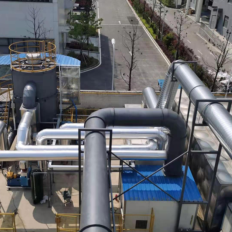
Overview Of Tower-Type RTO Our company offers two types of rotary RTO, which are the rotary RTO and the single barrel multi-valve RTO. The rotary RTO,...
See Details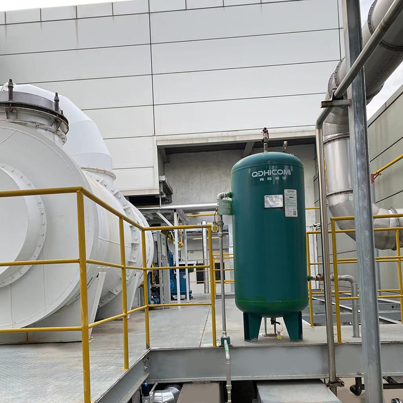
Overview Direct combustion high-temperature incineration equipment, abbreviated as TO, utilizes the heat generated by the combustion of auxiliary fuel...
See Details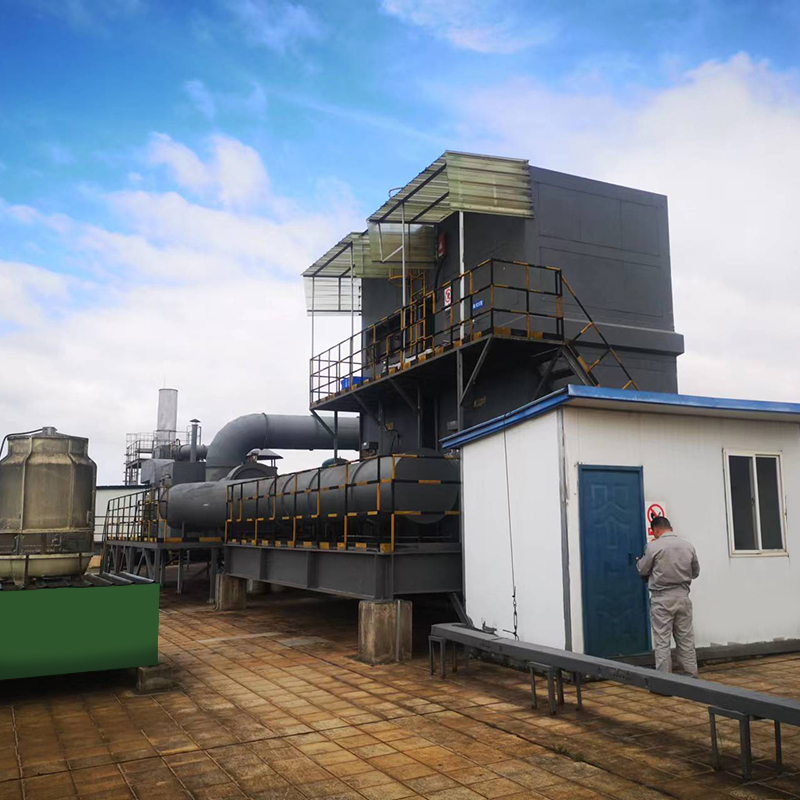
Overview Thermal storage catalytic oxidation (Regenerative Catalytic Oxidizer/RCO) is an organic waste gas treatment equipment that combines low-tempe...
See Details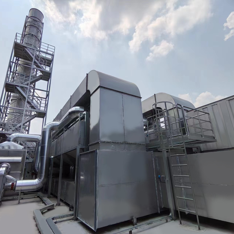
Overview of Activated Carbon Fiber Organic Solvent Purification Recovery Device The Activated Carbon Fiber Organic Solvent Purification Recovery Syste...
See Details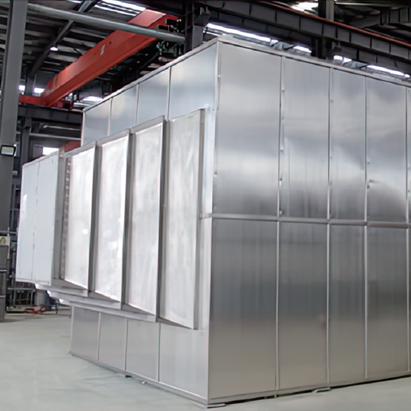
Product Introduction Gas heat exchanger is mainly used for energy saving and emission reduction industries in the waste heat recovery of flue gas in v...
See Details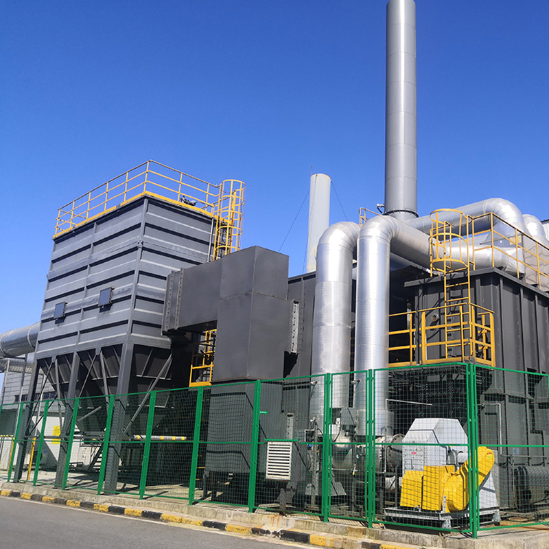
Concept Of Zeolite Wheel+RTO System Using zeolite wheel to adsorb organic waste gas, the low concentration and high air volume waste gas is concentrat...
See Details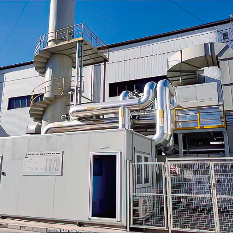
Concept Of Zeolite Rotary Wheel + Catalytic Combustion As A Set Of Equipment In the combined process of organic waste gas and waste gas treatment, the...
See Details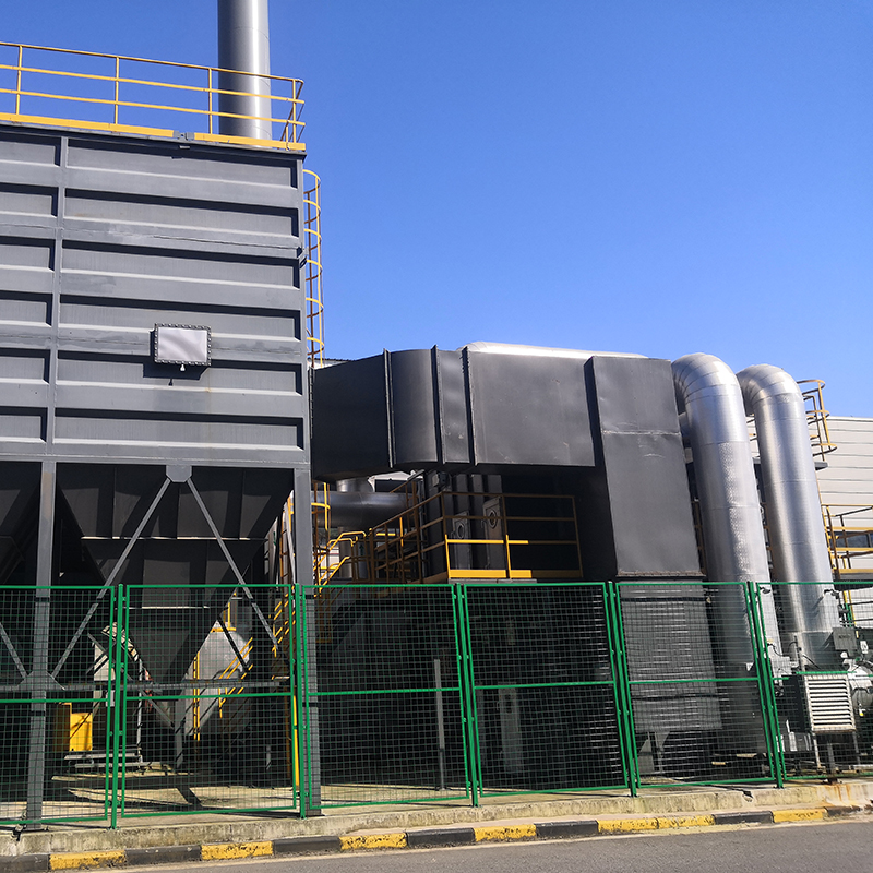
The Concept Of Zeolite Wheel+ Direct Combustion High-Temperature Incineration Equipment The purpose of employing rotary drum zeolite adsorption for or...
See Details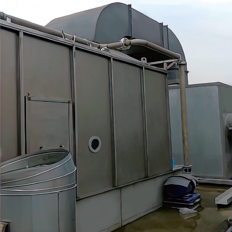
Overview The wet dust removal principle uses the process of capturing and separating dust particles in the gas phase by fully contacting gas-liquid tw...
See Details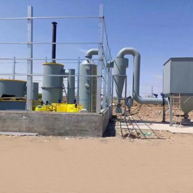
Overview Solid waste incineration furnaces are essential equipment in the management of solid waste, designed to transform waste materials into ash an...
See DetailsMOBILE
Product Manual

Copyright © Lv quan Environmental Protection Engineering Technology Co., Ltd. All Rights Reserved. Vocs Organic Waste Gas Treatment Engineering Equipment Manufacturer

