

 English
 русский
 Français
 Español
 عربى
عربى
LQ-RTO Heat-storage high-temperature incineration equipment
Cat:Equipment
Overview Of Tower-Type RTO Regenerative Thermal Oxidizer (RTO) is an organic waste gas treatment equipment that combines high-temperature oxidation wi...
See Details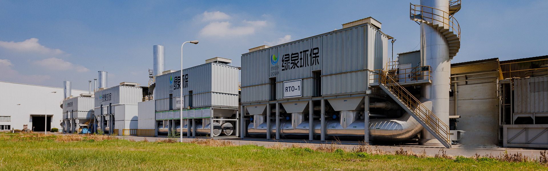
Content
Organic waste gas treatment engineering is the discipline of designing, building, and operating industrial systems that capture, convert, or destroy volatile organic compounds (VOCs) before exhaust air is released into the atmosphere. In most manufacturing environments, this means combining exhaust collection ductwork with a purification unit, commonly a regenerative thermal oxidizer, a regenerative catalytic oxidizer, an activated carbon adsorption system, or some combination of these, so that non-methane hydrocarbon concentrations at the stack meet applicable regulatory limits. The direct goal is measurable: convert organic pollutants into carbon dioxide and water vapor, or capture them for recovery, so that the treated air discharged from a facility complies with air quality standards. The rest of this article explains how that goal is achieved in practice, which technologies are typically selected for which conditions, how performance is measured, and how a facility can evaluate whether its current waste gas purification approach is adequate.
VOCs originate from a wide range of industrial processes, including painting and coating lines, printing operations, chemical and pharmaceutical manufacturing, plastics and rubber processing, semiconductor fabrication, and solvent-based cleaning. Left uncontrolled, these compounds react with sunlight and nitrogen oxides to form ground-level ozone and secondary particulate matter, both of which are regulated air pollutants. Because of this, environmental authorities including China's Ministry of Ecology and Environment and the United States Environmental Protection Agency have established emission-control frameworks that require covered facilities to install exhaust gas treatment equipment appropriate for their process conditions. Organic waste gas treatment engineering therefore sits at the intersection of environmental compliance, industrial process design, and mechanical engineering, and the technology selected for a given plant depends heavily on exhaust volume, VOC concentration, and the specific chemical composition of the waste stream.
Industrial organic waste gas treatment engineering relies on a relatively small set of proven technology families, each suited to different exhaust volumes, VOC concentrations, and compound types. Regenerative thermal oxidation (RTO) and regenerative catalytic oxidation (RCO) destroy VOC molecules through combustion, while activated carbon adsorption physically captures VOC molecules onto a porous medium for later recovery or disposal. Selecting between these approaches is rarely a matter of preference; it is driven by engineering variables such as airflow rate, VOC loading, moisture content, and whether the exhaust stream contains substances that could poison a catalyst or foul an adsorption bed. Understanding how these systems compare on destruction or removal performance is a useful starting point before moving into system design considerations.
A regenerative thermal oxidizer heats VOC-laden exhaust air to a high combustion temperature, typically in the range of 760°C to 1,100°C, so that organic molecules are oxidized into carbon dioxide and water vapor. Ceramic heat-exchange media inside the unit absorb heat from the treated air and release it back to incoming exhaust, which is what allows a properly sized RTO to operate with little or no supplemental fuel once it reaches steady-state conditions. This heat-recovery cycle is the defining feature of the regenerative design, distinguishing it from simpler direct-fired thermal oxidizers that vent heat rather than reusing it.
A regenerative catalytic oxidizer follows the same regenerative heat-exchange principle as an RTO but adds a catalyst bed that allows oxidation to occur at a substantially lower temperature, generally in the range of 300°C to 450°C rather than the 760°C-plus range needed for uncatalyzed thermal oxidation. Because the reaction proceeds at a lower temperature, an RCO system typically consumes less auxiliary fuel than a comparable RTO, which can make it attractive for exhaust streams with simple, non-catalyst-poisoning solvent compositions. The trade-off is that catalyst performance depends on exhaust cleanliness; particulates or specific chemical species can mask or deactivate the catalyst over time, so periodic catalyst inspection is part of routine maintenance planning for organic waste gas treatment engineering systems.
Activated carbon adsorption systems pass exhaust air through a bed of highly porous carbon that captures VOC molecules on its internal surface area rather than destroying them immediately. Once the carbon bed approaches saturation, it is regenerated, commonly with hot air, steam, or an inert gas purge, to desorb the captured VOCs, which can then be routed to a smaller oxidizer or recovery condenser. This approach is often selected for lower-concentration exhaust streams or for applications where solvent recovery has value, and it is frequently combined with a rotor concentrator to reduce the volume of air that a downstream oxidizer must handle.
The chart below summarizes how these three technology families compare on VOC destruction or removal efficiency, based on ranges reported across current industry technical literature. Efficiency figures for combustion-based systems such as RTO and RCO are commonly expressed as destruction removal efficiency, or DRE, which measures the percentage of inlet VOC mass that is converted before treated air leaves the stack. Adsorption-based systems are instead evaluated on removal efficiency, since VOC molecules are captured rather than chemically destroyed at the point of contact. Because real-world performance depends heavily on exhaust concentration, airflow uniformity, and equipment condition, the figures shown represent typical reported ranges rather than fixed values guaranteed for any single installation. Reviewing these ranges side by side helps explain why facility engineers weigh multiple technologies before finalizing an organic waste gas treatment engineering design.
Compiled from multiple industry technical publications on thermal, catalytic, and adsorption-based VOC control equipment.
As the chart illustrates, regenerative thermal oxidation and regenerative catalytic oxidation occupy a similarly high performance band, with destruction removal efficiency commonly reported between 95% and 99% depending on chamber configuration and residence time. Two-chamber RTO and RCO systems typically fall toward the lower end of that band, while three-chamber configurations or units fitted with an additional VOC entrapment stage can push destruction efficiency above 99% by reducing the untreated exhaust that can escape during valve switching. The similarity between RTO and RCO destruction performance is expected, since both rely on the same underlying oxidation chemistry; the meaningful difference between them lies in operating temperature and fuel consumption rather than final destruction efficiency. Activated carbon adsorption, by contrast, shows a much wider reported performance range, spanning from roughly 25% for very low-concentration, high-airflow streams up to more than 90% when the system is paired with concentration technology or an optimized bed design. This wide range exists because adsorption efficiency is highly sensitive to inlet VOC concentration, air humidity, molecular size, and how well the bed has been sized for the specific gas stream. In practice, this means a facility with dilute, high-volume exhaust may see lower standalone adsorption performance than one with a more concentrated, lower-volume stream. For this reason, many organic waste gas treatment engineering designs use adsorption as a concentration or pretreatment step rather than as the sole compliance technology for demanding permit limits. Facilities evaluating equipment options should treat these figures as a starting point for technology screening rather than as a substitute for site-specific engineering calculations and, where required, third-party stack testing. Regulatory permits typically specify a required destruction or removal efficiency directly, and the treatment technology chosen for a project needs to be capable of meeting that number under the facility's actual operating conditions, not only under idealized test conditions. Because performance data is reported by many independent engineering sources using different test methods and averaging conventions, cross-referencing multiple technical publications, as this article does, gives a more balanced picture than relying on a single source.
| Technology | Typical Operating Temperature | Reported Efficiency Range | Typical Best-Fit Application |
|---|---|---|---|
| Regenerative Thermal Oxidation (RTO) | 760°C - 1,100°C | 95% - 99%+ DRE | High-volume, continuous exhaust without catalyst-sensitive compounds |
| Regenerative Catalytic Oxidation (RCO) | 300°C - 450°C | 95% - 99% DRE | Simple solvent VOCs with low particulate content where lower fuel use is desired |
| Activated Carbon Adsorption | Ambient | 25% - 95% removal | Lower-concentration streams, solvent recovery, or pretreatment ahead of oxidation |
Before selecting waste gas treatment equipment, engineers first need to understand where VOC-laden exhaust is being generated within a facility, since collection design has as much influence on overall system performance as the treatment technology itself. Common sources include paint booths and coating lines, printing presses, chemical reactors and mixing tanks, solvent cleaning stations, and process vents associated with wastewater handling or solid waste storage. Industry exhaust from ongoing manufacturing processes represents the largest single application segment for VOC treatment systems, at roughly 45% of total application share according to a 2025 market analysis, followed by exhaust associated with water pollution control processes at close to 30%. Solid waste treatment operations and other smaller categories account for the remaining share. Mapping these sources accurately at the design stage allows engineers to size collection ductwork, hoods, and treatment equipment correctly rather than over- or under-sizing the system.
The donut chart below breaks down reported VOC treatment system application segments by category, drawing on a recent market analysis of the VOCs treatment systems industry. Industrial exhaust, meaning direct process vents from manufacturing operations such as coating, printing, and chemical processing, represents the largest application segment shown. Water pollution control applications, which include VOC stripping from wastewater treatment processes, form the second-largest segment. Solid waste treatment applications, covering vent gas from waste handling and storage operations, make up a smaller but still meaningful share. The remaining "other" category captures a range of smaller or mixed-source applications that do not fall cleanly into the three main groups.
Source: compiled from a 2025 VOCs treatment system market analysis; segment shares are approximate.
This distribution matters for organic waste gas treatment engineering because it shows that the majority of installed treatment capacity is still tied directly to active manufacturing exhaust rather than to secondary or incidental sources. A facility running continuous coating, printing, or chemical processing lines should expect its waste gas treatment system to be sized primarily around that core process exhaust, since it represents the largest and most consistent VOC load in most industrial settings. Water pollution control applications form the second-largest segment because VOC stripping from wastewater and process water is common in chemical, pharmaceutical, and petrochemical facilities, where dissolved organics volatilize during aeration or treatment. Solid waste treatment sources, while smaller in overall share, are increasingly relevant as facilities manage odor and emission control at waste storage and handling areas, particularly where nearby communities are sensitive to fugitive odor complaints. The "other" category reflects the reality that VOC sources in industrial facilities are rarely confined to a single, easily labeled process; tank farms, transfer operations, and maintenance activities can all contribute intermittent organic emissions. For engineering purposes, this segmentation reinforces the importance of a full source inventory before equipment selection, since a system designed only around the largest exhaust source may leave smaller but still regulated emission points uncontrolled. It also explains why many organic waste gas treatment engineering projects combine multiple collection points into a single centralized treatment system rather than installing separate equipment at every source, which can improve both capital efficiency and treatment consistency. Facilities in industries such as printing, coatings, and chemical manufacturing typically see the industrial exhaust category dominate their VOC inventory, while facilities with significant wastewater or solid waste handling operations may need to plan additional capacity for those secondary sources. Recognizing which segment a facility's emissions fall into also helps in comparing performance benchmarks, since destruction efficiency requirements and monitoring approaches can differ between continuous process exhaust and more intermittent secondary sources. Ultimately, accurate source segmentation supports better system design decisions and more realistic compliance planning across the full scope of a facility's organic waste gas emissions.
Demand for organic waste gas treatment engineering has grown steadily over the past decade, driven primarily by tightening air quality regulations rather than by any single technology breakthrough. According to one 2025 market research estimate, the global VOCs treatment market was valued at approximately USD 4.52 billion in 2024 and is projected to reach roughly USD 7.12 billion by 2033, reflecting a compound annual growth rate of about 5.4%. This growth trajectory tracks closely with the expansion of manufacturing capacity in developing economies alongside stricter enforcement of existing air pollution rules in established industrial regions. Regulatory bodies including the EPA in the United States and China's Ministry of Ecology and Environment have both continued to tighten requirements around fugitive and stack VOC emissions, pushing facilities that previously operated without dedicated treatment equipment toward compliance investment.
The area chart below traces an approximate market growth trajectory for the global VOCs treatment sector between 2024 and 2033, interpolated from the beginning and end figures reported in the cited market analysis. The chart is intended to illustrate the general direction and pace of growth rather than to represent precise year-by-year revenue figures, since most published market reports only disclose starting-year and ending-year values along with an average annual growth rate. Even a moderate compound annual growth rate compounds meaningfully over a nine-year window, which is visible in the widening gap between early and late years on the chart. This growth pattern is consistent with related market segments, including VOC recovery and abatement equipment, which independent analyses have also projected to expand at comparable or higher rates over similar time horizons. Viewing the trend visually helps put the scale of ongoing investment in organic waste gas treatment engineering into perspective.
Interpolated between the 2024 and 2033 figures reported in a 2025 VOCs treatment market analysis; intermediate years are approximate.
The upward trend shown in the chart reflects several converging forces rather than a single driver. First, regulatory tightening has expanded the range of facilities required to install treatment equipment, particularly as fugitive emission standards such as China's GB 37822-2019 extend monitoring and control obligations to storage, transfer, and process equipment that were previously less closely regulated. Second, industrial output in sectors that generate significant VOC emissions, including chemical manufacturing, printing, coatings, and pharmaceuticals, has continued to expand in many regions, directly increasing the total volume of exhaust requiring treatment. Third, aging equipment installed during earlier compliance cycles is gradually being replaced or upgraded, since destruction efficiency requirements in newer permits are often more stringent than those in place when older systems were first installed. Fourth, growing awareness of the health effects associated with VOC exposure, including respiratory and neurological effects documented by environmental health agencies, has increased pressure on facilities to address emissions proactively rather than waiting for enforcement action. It is worth noting that market growth figures like these are projections based on modeling assumptions and should be read as directional indicators rather than guaranteed outcomes, since actual growth can be affected by economic cycles, regulatory timing, and regional policy differences. For facility engineers and plant managers, the practical takeaway from this trend is less about the exact figures and more about the underlying signal: regulatory and market pressure on organic waste gas emissions is trending in one direction, and facilities that plan treatment upgrades proactively are generally better positioned than those that wait until a permit renewal forces the decision. Asia Pacific has been identified in multiple market analyses as a fast-growing region for VOC treatment investment, which aligns with the pace of industrialization and simultaneous regulatory tightening occurring across several Asian manufacturing economies, including China. This regional growth pattern is directly relevant to facilities operating in or sourcing equipment from Chinese industrial regions, where both manufacturing volume and environmental enforcement have increased in parallel. Understanding this broader market and regulatory context helps facility decision-makers evaluate whether a proposed waste gas treatment engineering investment is keeping pace with the trajectory that peer facilities in their industry are likely to follow.
Once a technology has been selected, the practical question for plant engineers becomes how to verify that an installed organic waste gas treatment engineering system is actually performing as designed. Two indicators dominate almost every technical evaluation: destruction removal efficiency (DRE), which measures the percentage of inlet VOC mass eliminated, and thermal energy recovery, which measures how efficiently a regenerative system reuses heat rather than consuming supplemental fuel. Both figures are typically confirmed through stack testing conducted with recognized reference methods, comparing VOC concentration at the inlet and outlet of the treatment unit under representative operating conditions. Other supporting indicators include residence time in the combustion or catalyst zone, valve switching integrity in regenerative systems, and pressure drop across adsorption beds, all of which influence whether headline efficiency figures hold up in continuous operation rather than only during initial commissioning tests.
The gauge below illustrates a single representative indicator commonly cited for well-designed regenerative thermal oxidation systems: thermal energy recovery, sometimes referred to as thermal efficiency. Thermal energy recovery describes the proportion of heat contained in the treated exhaust stream that the ceramic heat-exchange media successfully capture and transfer back to incoming untreated air. Industry technical sources commonly report that properly designed regenerative systems can reach thermal energy recovery of up to approximately 97% under suitable operating conditions. This figure is distinct from destruction removal efficiency, and the two indicators should always be reviewed together rather than interchangeably when assessing system performance. The gauge format is used here because thermal energy recovery is most meaningfully understood as a single performance ceiling relative to a 0-to-100% scale, rather than as a trend over time.
Based on commonly reported thermal efficiency figures for well-designed regenerative thermal oxidation systems.
A thermal energy recovery figure approaching 97% means that only a small fraction of the heat generated during VOC oxidation needs to be replaced by supplemental fuel once the system reaches stable operating temperature, which is why well-designed regenerative systems can often run with minimal auxiliary burner use after startup. This matters directly for organic waste gas treatment engineering because energy recovery efficiency, alongside destruction efficiency, determines whether a system can sustain compliant operation over its full service life rather than only during initial testing. Systems that fall well short of their design thermal efficiency typically show signs such as increased burner run time, higher exhaust stack temperatures than expected, or inconsistent valve cycling, any of which should prompt an engineering review rather than being dismissed as normal wear. It is also worth noting that thermal energy recovery tends to decline gradually over years of operation as ceramic heat-exchange media accumulate particulate fouling or as seals and valves wear, which is why routine maintenance and periodic performance verification are considered standard practice in a well-run facility. Because thermal efficiency and destruction efficiency interact, a system can in principle maintain high VOC destruction while thermal efficiency degrades, simply by consuming more supplemental fuel to compensate, so relying on destruction efficiency alone as a health check can mask a developing energy-recovery problem. For this reason, many facility engineers track thermal energy recovery alongside DRE as part of routine monitoring rather than treating stack testing as a one-time commissioning exercise. Chamber configuration also affects achievable thermal efficiency; three-chamber regenerative designs and units with additional heat-exchange media depth can typically sustain performance closer to the higher end of the reported range than simpler two-chamber configurations. Facilities evaluating a new or upgraded system should ask equipment engineers for documented thermal efficiency figures under conditions representative of their actual exhaust volume and VOC concentration, rather than relying solely on figures quoted for optimal conditions. Because thermal energy recovery directly affects ongoing fuel consumption, it is one of the few technical performance indicators in organic waste gas treatment engineering that connects environmental compliance directly to operating efficiency, making it a natural point of alignment between environmental and operations teams within a facility. Reviewing this single indicator in gauge format, as shown here, is a useful way to communicate system health to stakeholders who may not need the full complexity of a stack test report but do need a clear read on whether the system is operating within its designed performance envelope.
Selecting a treatment technology is only one part of organic waste gas treatment engineering; the surrounding system design often determines whether that technology performs as expected once installed. Key design variables include exhaust volume and its variability over a production cycle, VOC concentration and composition, moisture content, temperature, and the presence of particulates or corrosive compounds that could affect equipment materials. Ductwork routing and hood design at the collection point influence both capture efficiency and the energy required to move exhaust air to the treatment unit, while control system design determines how reliably the equipment responds to fluctuating production conditions rather than only steady-state test conditions. A well-engineered system accounts for all of these variables together rather than optimizing the treatment unit in isolation from the rest of the exhaust handling system.
The schematic below illustrates, in general terms, the major functional zones found in a typical regenerative-type organic waste gas treatment unit, from exhaust intake through to clean air discharge. It is intended as an illustrative engineering reference rather than a drawing of any single specific installation, since actual equipment layout varies by manufacturer, airflow capacity, and site constraints. Numbered callouts correspond to the functional zone descriptions listed beneath the diagram.
Illustrative isometric schematic of a typical regenerative-type organic waste gas treatment unit; generic engineering reference, not a specific product drawing.
Facility engineers evaluating a new system typically request documentation covering airflow capacity, chamber configuration, control logic, and materials of construction, since each of these affects long-term reliability under real operating conditions rather than only initial performance test results. Systems intended for continuous operation are generally engineered with redundant safety interlocks, explosion-relief provisions where lower explosive limit margins are a concern, and accessible maintenance points for valve and media servicing. Because production conditions fluctuate, well-engineered systems are also designed with a reasonable turndown ratio, allowing stable operation across a range of airflow rates rather than only at a single design point.
Organic waste gas treatment engineering does not happen in a regulatory vacuum; equipment selection and system design are shaped directly by the emission standards a facility must meet. In China, GB 37822-2019, the national standard for fugitive emission of volatile organic compounds, requires covered facilities to monitor total volatile organic compounds (TVOC) or non-methane hydrocarbons (NMHC) at defined points and to implement control measures for storage, transfer, and process equipment. The standard also references related national standards, including GB 16297 for comprehensive air pollutant emissions, and establishes monitoring methodologies that facilities and third-party testing organizations are expected to follow when demonstrating compliance.
In the United States, thermal and catalytic oxidation technologies are recognized under the Clean Air Act framework as proven control technologies capable of meeting Maximum Achievable Control Technology (MACT) standards for facilities that emit hazardous air pollutants listed on the EPA's federal registry. Permit conditions in both regulatory contexts commonly specify a required destruction or removal efficiency directly, which is one reason facility engineers place so much emphasis on documented DRE and thermal efficiency figures when selecting equipment, as discussed earlier in this article. Compliance verification typically relies on stack testing performed by qualified third-party firms using standardized reference methods, rather than on equipment specification sheets alone.
A peer-reviewed analysis of VOC emissions from China's refining industry, published in the journal Aerosol and Air Quality Research, offers a useful illustration of why source-specific engineering matters. The study estimated total VOC emissions of roughly 541 gigagrams from surveyed refineries in a recent reporting year, with fugitive sources alone contributing close to 44% of that total, alongside smaller shares from end-of-pipe process vents, tank storage, and wastewater treatment. Alkanes made up the largest share of emitted compounds by mass in that study, while alkenes, despite a smaller mass share, were identified as the largest contributor to ozone formation potential due to their higher atmospheric reactivity. This kind of source- and compound-level detail illustrates why organic waste gas treatment engineering projects benefit from a proper emissions inventory before equipment is selected, since a system designed only around the largest exhaust source by volume may still leave a highly reactive but lower-volume compound inadequately controlled.
Lvquan Environmental Protection Engineering Technology Co., Ltd. is based in Gaoyou, a city in Yangzhou, Jiangsu Province, often described as the northern gateway to the province. The company was established as a joint-stock enterprise by a team with more than 30 years of combined experience in VOCs equipment design and manufacturing, and it operates as a dedicated organic waste gas treatment engineering equipment manufacturer. With a registered capital of 22 million yuan, fixed assets of nearly 40 million yuan, and total assets approaching 60 million yuan, the company maintains a 9,800-square-meter production facility equipped with more than 200 sets of machining equipment. A workforce of roughly 120 employees supports an annual production capacity valued at approximately 100 million yuan, reflecting a manufacturing scale built specifically around industrial VOC and organic waste gas treatment equipment.
This combination of long-tenured engineering experience and dedicated manufacturing capacity allows the company to focus specifically on organic waste gas treatment engineering equipment for VOC-emitting industries, rather than treating air pollution control as one product line among many unrelated categories. Facilities evaluating a waste gas treatment engineering partner often look for exactly this kind of specialization, since equipment reliability over years of continuous operation depends heavily on design experience specific to VOC applications rather than general industrial fabrication background.
Both technologies use regenerative heat exchange to recover thermal energy, but an RTO relies purely on high-temperature combustion while an RCO adds a catalyst that allows oxidation to occur at a substantially lower operating temperature, typically reducing auxiliary fuel use.
DRE is measured by comparing VOC concentration at the inlet and outlet of a treatment system, usually through stack testing performed with standardized reference methods, and is expressed as the percentage of inlet VOC mass eliminated.
It depends on exhaust concentration and permit limits; standalone adsorption performance varies widely with VOC concentration, so many facilities pair adsorption with a concentration stage or oxidizer when permit limits are demanding.
Requirements depend on exhaust volume, VOC composition, applicable regulatory standards such as GB 37822-2019 or EPA-based permit conditions, and the specific industry a facility operates in, so equipment must be engineered around site-specific conditions rather than a single standard configuration.
Most engineering guidance recommends routine inspection of valves, heat-exchange media, and, for RCO systems, catalyst condition on a scheduled basis, alongside periodic stack testing, since performance can gradually decline with normal operating wear.
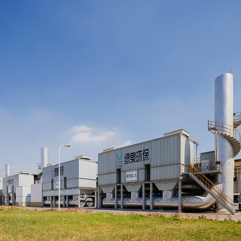
Overview Of Tower-Type RTO Regenerative Thermal Oxidizer (RTO) is an organic waste gas treatment equipment that combines high-temperature oxidation wi...
See Details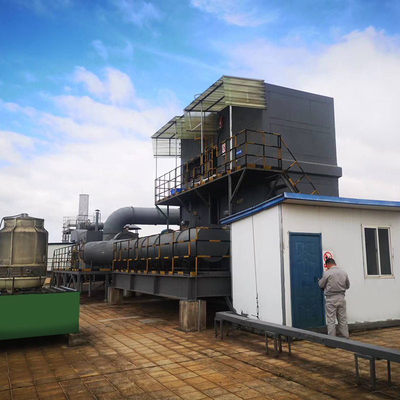
Overview Thermal storage catalytic oxidation (Regenerative Catalytic Oxidizer/RCO) is an organic waste gas treatment equipment that combines low-tempe...
See Details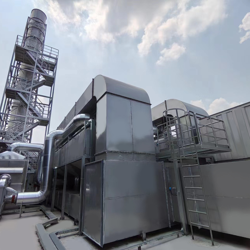
Overview of Activated Carbon Fiber Organic Solvent Purification Recovery Device The Activated Carbon Fiber Organic Solvent Purification Recovery Syste...
See Details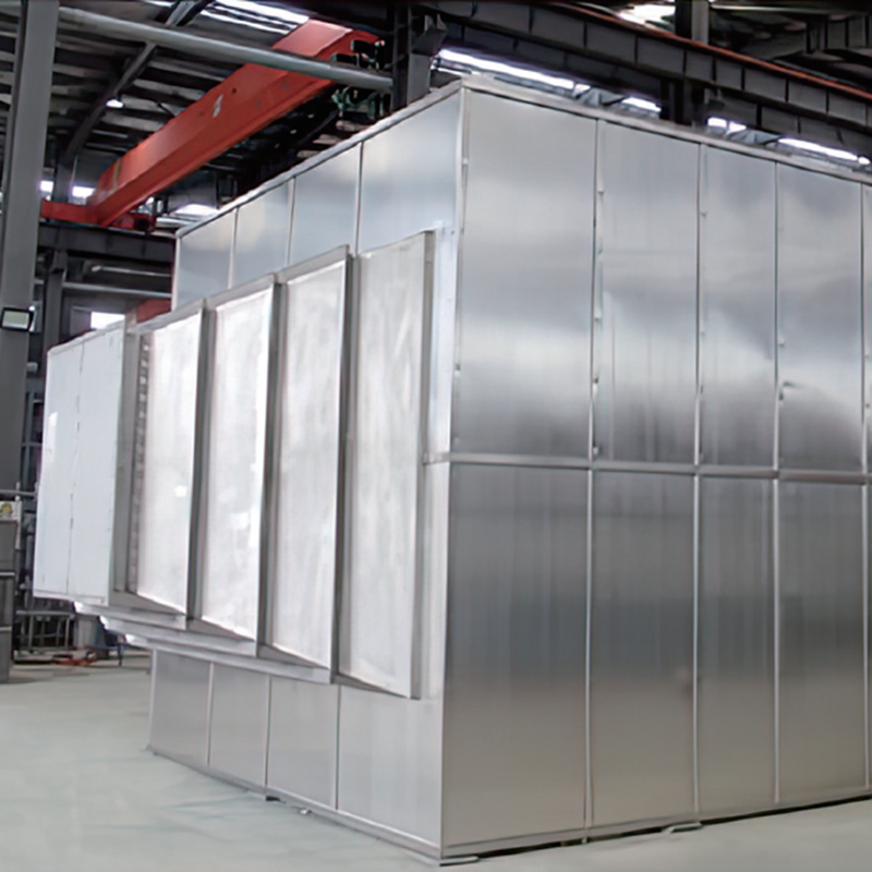
Product Introduction Gas heat exchanger is mainly used for energy saving and emission reduction industries in the waste heat recovery of flue gas in v...
See Details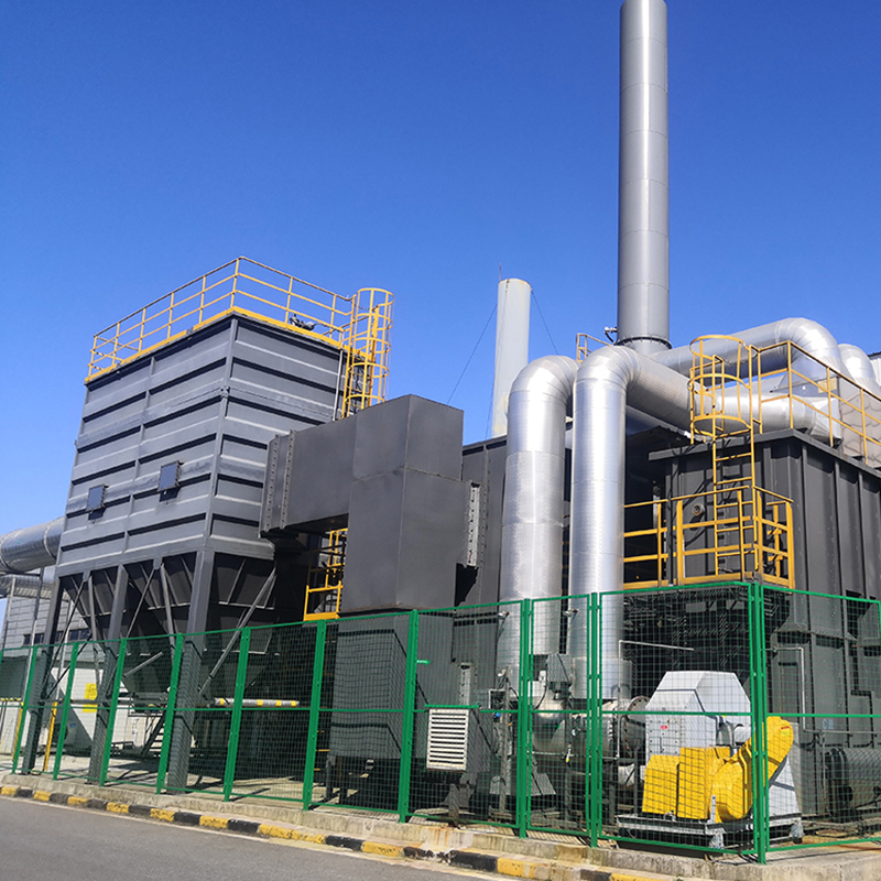
Concept Of Zeolite Wheel+RTO System Using zeolite wheel to adsorb organic waste gas, the low concentration and high air volume waste gas is concentrat...
See Details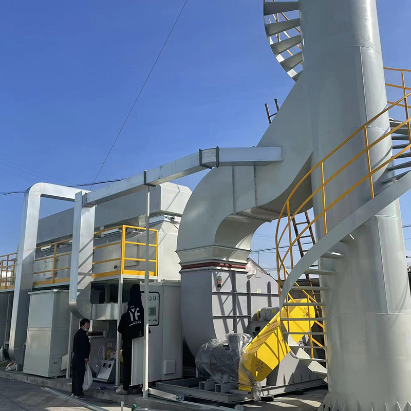
The VOC-CFT-CO Adsorption Catalytic Purification Equipment The VOC-CFT-CO adsorption catalytic purification equipment, consisting of fixed-bed honeyco...
See Details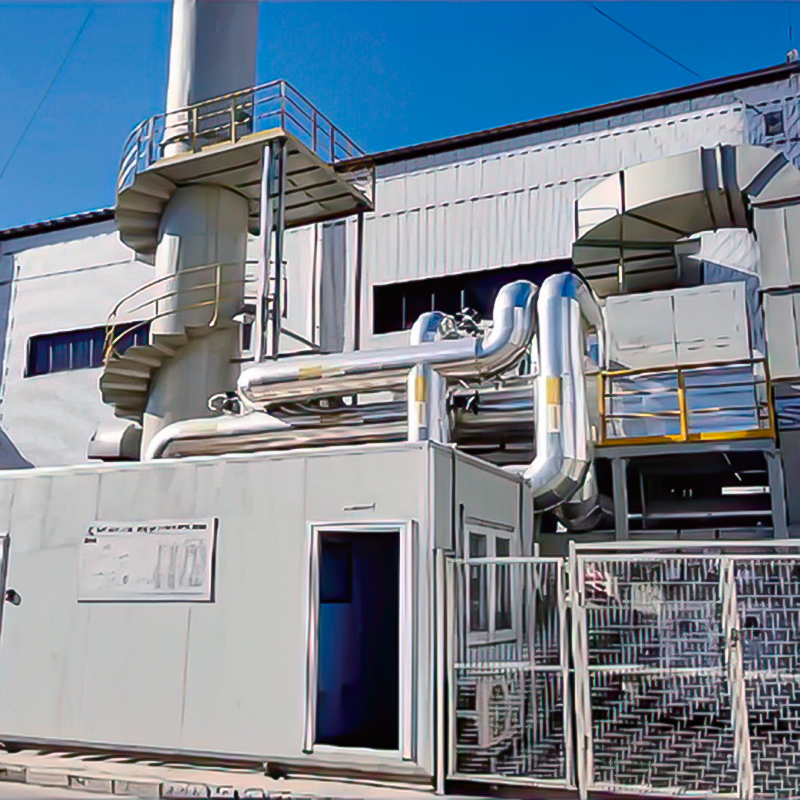
Concept Of Zeolite Rotary Wheel + Catalytic Combustion As A Set Of Equipment In the combined process of organic waste gas and waste gas treatment, the...
See Details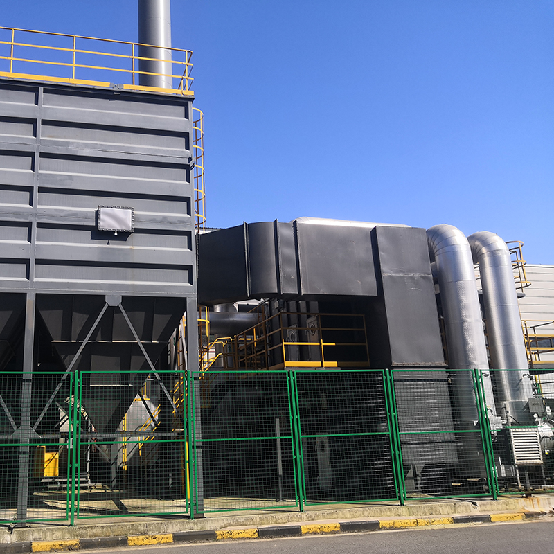
The Concept Of Zeolite Wheel+ Direct Combustion High-Temperature Incineration Equipment The purpose of employing rotary drum zeolite adsorption for or...
See Details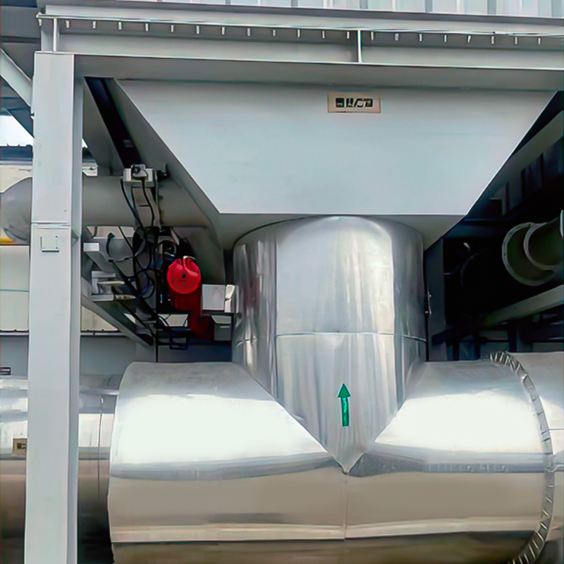
Purpose Mainly used for proportional ventilation of high-temperature flue gas. lt is widely used in places where leak rate requirements are not high, ...
See Details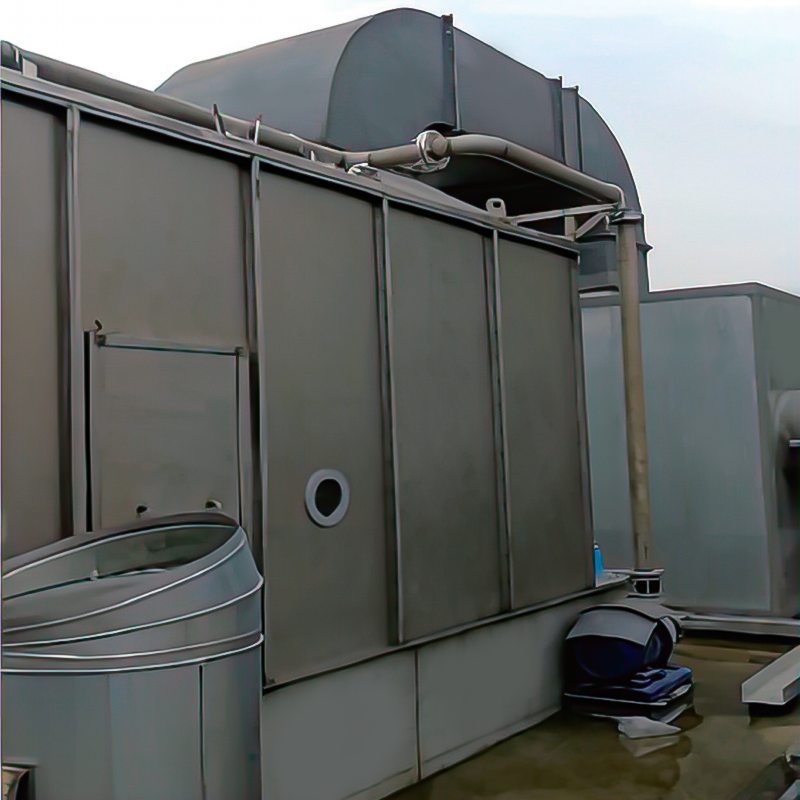
Overview The wet dust removal principle uses the process of capturing and separating dust particles in the gas phase by fully contacting gas-liquid tw...
See DetailsMOBILE
Product Manual

Copyright © Lv quan Environmental Protection Engineering Technology Co., Ltd. All Rights Reserved. Vocs Organic Waste Gas Treatment Engineering Equipment Manufacturer

