

 English
 русский
 Français
 Español
 عربى
عربى
LQ-RTO Heat-storage high-temperature incineration equipment
Cat:Equipment
Overview Of Tower-Type RTO Regenerative Thermal Oxidizer (RTO) is an organic waste gas treatment equipment that combines high-temperature oxidation wi...
See Details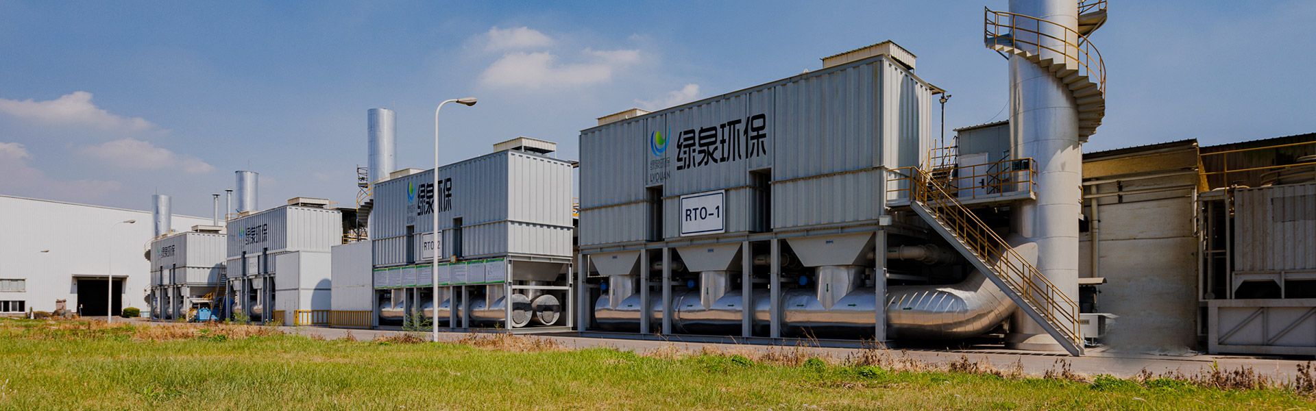
Content
Stand beside the curing oven of a dip-spin zinc-flake coating line and the problem is easy to locate. The smell does not come from the wet parts on the carrier; it comes from the oven exhaust, where the solvent that carried the coating is driven out of the parts at 180 to 260 degrees Celsius. That exhaust is modest in volume, hot, and loaded with xylene, butyl acetate, alcohols and glycol ethers. Fifteen metres away, the coating room extraction fan is pulling 20,000 cubic metres an hour of very nearly the same solvent, diluted fifteen or twenty times over.
Most fastener plants discover that difference the hard way, usually a few weeks after a stack test. Non-methane hydrocarbon limits on coating, painting and surface treatment lines have tightened across Jiangsu, Zhejiang, Hebei and Guangdong, and boundary odour complaints that were once tolerated now trigger inspections. A regenerative thermal oxidizer is the standard answer, and in fastener manufacturing it is usually the right answer. The oxidizer itself, however, is almost never the part of the system that fails.
Here is the conclusion up front, before any of the engineering: for a fastener plant, RTO performance is decided upstream of the burner. What arrives at the ceramic heat exchange media, at what temperature, at what particulate load, and with what trace of silicon or phosphorus, determines whether the oxidizer runs for ten years or plugs in eighteen months. Combustion chamber temperature and residence time are the easy variables to control. Stream conditioning is the difficult one, and it is where projects are won or lost.
This guide walks through the whole chain as it applies to bolts, screws, nuts, washers, studs and formed fasteners: where the volatile organic compounds actually come from, how to characterise the exhaust before sizing anything, how to pre-treat it, which oxidation platform fits which stream, what to specify, what it costs to run, how to keep it compliant, and how to choose the company that builds it.
A regenerative thermal oxidizer on a fastener line succeeds or fails on pre-treatment, not on combustion temperature.
A fastener plant is not one emission source, it is six or seven of them, and only two or three are genuine thermal oxidation jobs. Confusing them is the single most common cause of an oversized, over-priced, under-performing abatement system. A heading machine throws oil mist, a quench tank throws oil vapour, a phosphating line throws acid mist, and a dip-spin coating line throws solvent. Treating all of them with one oxidizer, through one duct, is technically possible and commercially unwise.
The table below is the map most process engineers wish they had been given before the first quotation arrived.
| Process step | Dominant pollutant | Conventional control | Is this an RTO job? |
|---|---|---|---|
| Wire drawing and lubricant application | Oil mist, condensable lubricant vapour, low VOC mass | Baffle separator plus mist eliminator | No. High particulate and low VOC make oxidation uneconomic |
| Heading, threading, forming, cold forging | Coolant and lubricant mist | Enclosed machines with local mist collection | No. Shares plant extraction but should not share the oxidizer duct |
| Heat treatment, quench and temper | Quench oil mist, cracked hydrocarbons, ammonia where nitriding is used | Electrostatic precipitator, wet scrubber, or both | Partly. Cracked organics can be oxidised, but oil mist must be removed first |
| Degreasing, solvent wipe, ultrasonic cleaning | Hydrocarbon or chlorinated solvents | Condensation, activated carbon adsorption, closed-loop recovery | Sometimes. Halogenated solvents demand special materials and much higher temperature |
| Dip-spin or dip-drain zinc-flake coating | Xylene, butyl acetate, alcohols, glycol ethers, fine coating solids | Capture at oven and coating room, then thermal oxidation | Yes. This is the dominant RTO load in most fastener plants |
| Spray painting, touch-up, marking | Aromatic and ester solvents, overspray solids | Dry booth filtration or water curtain, then oxidation | Yes, usually after concentration |
| Pre-applied thread-locking adhesive curing | Trace solvents and residual monomer, strong odour at very low concentration | Local exhaust, small oxidizer or adsorption polishing | Occasionally. Volume is low but odour impact can be high |
| Phosphating, pickling, passivation | Acid mist, no meaningful VOC | Wet scrubber | No. Acid mist must never reach the oxidizer internals |
Take the two coating streams from the opening paragraph. The oven exhaust might be 2,500 cubic metres an hour at 2,000 milligrams per cubic metre. The coating room exhaust might be 20,000 cubic metres an hour at 250 milligrams per cubic metre. Combined, you have 22,500 cubic metres an hour at roughly 445 milligrams per cubic metre: a large, dilute stream that cannot sustain autothermal operation and that requires a physically enormous oxidizer to treat.
Kept separate, the oven stream alone can feed a compact oxidizer that runs with little or no supplementary fuel, and the dilute coating room stream can be concentrated on a zeolite rotor before a much smaller oxidation stage, or handled by a different route entirely. The ductwork decision, made at the drawing stage, changes capital cost by a factor of two and annual gas consumption by a factor of three or more.
Capture efficiency matters just as much as stream separation. A coating room with a well-designed push-pull envelope captures 90 to 95 percent of the solvent released. A room with an open door, a cross-draught and one extraction grille on the far wall captures perhaps 60 percent. The difference does not show up in the oxidizer specification, but it shows up on the fence-line monitor and in the stack test result, because fugitive emissions are counted as part of the site total.
Never blend a small concentrated coating-oven stream with a large dilute coating-room stream; keep them separate and size the oxidizer on the concentrated one.
Oxidizer quotations are frequently built on a flow rate guessed from a fan nameplate and a concentration guessed from a material safety data sheet. That is how a plant ends up with an oxidizer that is 40 percent oversized on day one and thermally unstable once production changes. A proper characterisation takes one to three weeks and costs a fraction of the equipment it protects.
The measurements that actually determine the design are these: volumetric flow at the capture point, both average and peak; VOC concentration as total non-methane hydrocarbon and as a species profile; exhaust temperature and its variation across the cycle; moisture content; particulate concentration and particle size distribution; and the presence of catalyst or media poisons such as silicon, phosphorus, sulphur, halogens and alkali metals.
Two further quantities matter for safety rather than performance: the lower explosive limit of the solvent mixture, and the rate at which concentration can change when a basket enters or leaves the oven. Dip-spin curing is a batch process. Concentration at the oven outlet can triple within ninety seconds and fall back just as quickly, which is exactly why continuous lower-explosive-limit monitoring with a fast-response sensor is specified rather than a periodic sample.
The chart below summarises the concentration ranges seen across fastener plant exhaust streams. It is worth reading twice, because the shape of the bars explains most of the design decisions that follow.
Typical VOC concentration by fastener process exhaust stream (mg/m3)
The first thing the chart shows is the sheer spread: two orders of magnitude between the curing oven and the temper exhaust. No single abatement platform is optimal across that whole range, which is why the fastener industry ends up using RTO, catalytic oxidation, concentration plus oxidation and scrubbing side by side in the same building.
The second thing it shows is that the curing oven is the only stream that reliably pays for itself. At 1,200 to 3,000 milligrams per cubic metre, a well-recuperated regenerative thermal oxidizer reaches autothermal operation and stops needing meaningful supplementary fuel. Below roughly 1,500 milligrams per cubic metre, the fuel bill becomes a visible line item on the plant's monthly energy report.
The third observation concerns volume rather than concentration, and it is the one the chart cannot show directly. The curing oven stream is small, perhaps 1,500 to 4,000 cubic metres an hour on a medium-sized dip-spin line. The coating room extraction is large, typically 15,000 to 40,000 cubic metres an hour. Multiplying the two charts by their respective flows gives the mass emission rate, and the dilute stream frequently carries as much solvent mass as the concentrated one, simply because there is so much more of it.
That is the argument for splitting the streams and applying concentration technology to the dilute one. A zeolite rotor concentrating the coating room stream by a factor of ten reduces the flow entering the oxidizer from 25,000 cubic metres an hour to about 2,500, which shrinks the oxidizer, the burner, the fan and the foundation accordingly.
The fourth point is about variability. Batch curing means the design concentration is not the average but something close to the peak, because the lower-explosive-limit interlock is set against the peak. A stream averaging 900 milligrams per cubic metre that peaks at 3,500 dictates a different safety configuration from a genuinely steady stream at the same average, even though the sizing calculation looks similar.
Fifth, moisture deserves attention in plants that run a wet scrubber upstream. Saturated exhaust at 60 degrees Celsius carries a large latent heat load into the oxidizer, and if the duct runs are long and uninsulated, condensate will pool in low points, corrode carbon steel and drip into the burner chamber. Insulated ducts with drain legs and a demister at the scrubber outlet are inexpensive insurance.
Sixth, particulate measurement is not optional in coating plants. Zinc-flake coatings contain metallic particles, and spray booths generate overspray solids even after dry filters. A concentration of 5 milligrams per cubic metre of fine particulate seems trivial until it accumulates on ceramic media over 6,000 operating hours and raises pressure drop by 150 percent.
Seventh, the species profile determines materials of construction. A stream containing chlorinated solvent demands a much higher oxidation temperature, a quench or heat exchanger after the chamber, and corrosion-resistant alloys in the cold sections. A stream containing silicon demands that the source be eliminated, not treated.
Eighth, the lower-explosive-limit calculation should be done on the actual mixture, not on the single dominant solvent. Fastener coatings often blend xylene with butyl acetate, ethanol and a glycol ether, and each component has a different lower explosive limit and a different response factor on the sensor. A sensor calibrated on xylene alone can misread a mixed stream by 30 percent or more.
Ninth, the sampling location matters more than the sampling method. Taking a sample from a duct that has not yet mixed properly, or from a point where the fan has already diluted the stream with room air, produces numbers that are quietly wrong and financially expensive to correct later.
Tenth, the characterisation report should state the design basis explicitly, including the assumed production schedule, the assumed coating consumption rate and the assumed capture efficiency, so that when production changes, the plant knows whether the oxidizer margin still holds.
Size the oxidizer on measured peak concentration and measured peak flow, never on a nameplate fan rating or a material safety data sheet.
Three contaminants cause the majority of premature failures in fastener coating applications: coating solids, silicon and phosphorus compounds, and high-boiling solvents that condense on cool surfaces. Each has a different removal method, and each is cheaper to remove upstream than to manage inside the oxidizer.
Zinc-flake coatings contain metallic powder, and air-atomised or dip-spin processes liberate a fine fraction that stays airborne long enough to reach the oxidizer duct. A cyclone alone is not sufficient for particles below ten micrometres. The usual arrangement is a baffle or settling chamber to remove the coarse fraction, followed by a high-efficiency filter stage, followed by a wet scrubber where the stream is hot and sticky. Filter media selection matters: standard pleated filters blind quickly with coating solids, and a pre-coat of lime or diatomaceous earth extends cartridge life considerably.
For fastener plants where the exhaust is hot, loaded with fine coating dust and mildly acidic, a horizontal spray scrubber installed immediately after the oven outlet does three jobs at once. It cools the gas to a temperature the downstream equipment can tolerate, it captures the fine particulate into the water phase, and it absorbs residual acid species that would otherwise attack ductwork and cold-side steelwork. It also provides a buffer against concentration spikes, because the water volume damps short-term variation.
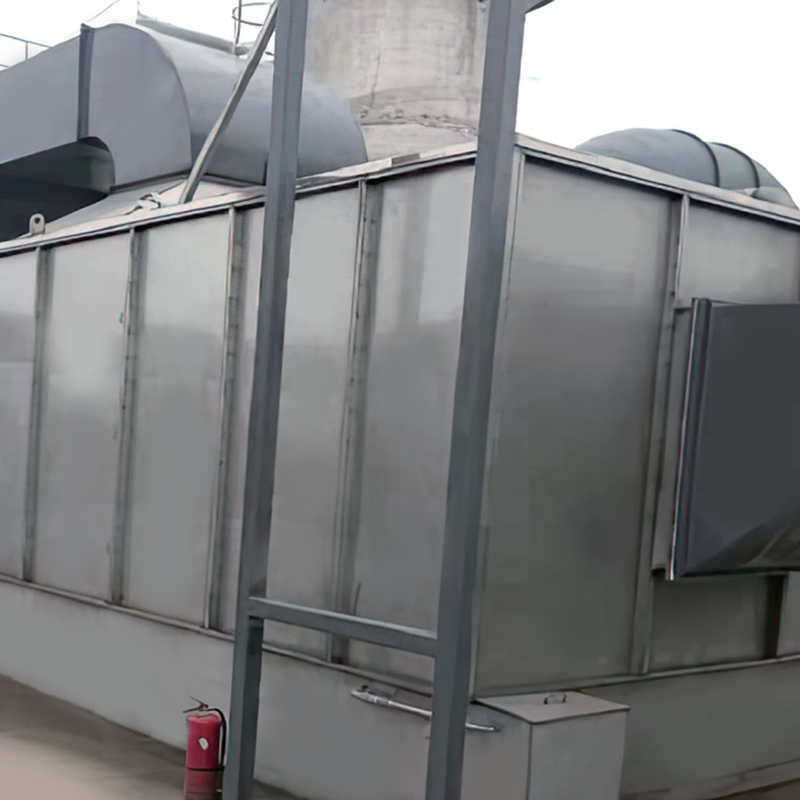 LQ-WPG Horizontal spray cabinetThe horizontal spray cabinet is equipped with two water curtains inside. The first is a rectangular stainless steel perforated plate and the second is a non-perforated...View Product →
Some drawing lubricants, release agents and anti-foam additives contain silicone. At combustion temperature, silicone oxidises to silicon dioxide, which is a glass. It does not pass through the ceramic heat exchange media; it deposits on the surface, fuses at operating temperature, and progressively blinds the channels. The same mechanism applies to phosphorus, which forms low-melting phosphate glasses. Once silica glass forms, no amount of bake-out or compressed-air purging removes it. The media must be replaced, and the replacement cost on a large oxidizer is substantial.
The correct response is substitution rather than treatment. Audit every lubricant, release agent, cleaning solvent and coating additive that can reach the duct, and require silicone-free formulations where alternatives exist. Where substitution is impossible, expect to inspect media annually rather than biennially and to budget for partial replacement.
Glycol ethers, high-boiling esters and some coupling agents condense in the cold inlet plenum and on the first layers of ceramic media. The deposit is not burnt off by the normal cycle because it sits below the combustion chamber, at inlet temperature. Over months it restricts flow, raises pressure drop, and creates a fire load. Solutions include raising the inlet temperature above the dew point of the heaviest species, using a hot-gas recirculation loop into the inlet plenum, and specifying media geometry with wider channels on the inlet side.
Fastener plants often run phosphating, pickling and passivation in the same building as coating. If the general ventilation combines these areas, acid mist reaches the oxidizer. Even at low concentration, hydrochloric or sulphuric acid mist accelerates corrosion of the cold-end steel, the fan impeller and the stack. Segregating the ventilation systems is the practical fix; a wet scrubber on the acid lines is the belt-and-braces version.
Silicone and phosphorus cannot be burnt out of ceramic media once they fuse; they must be eliminated at source or removed before the oxidizer inlet.
Once the stream is characterised and pre-treated, the platform choice becomes relatively straightforward. Fastener plants work with a small number of configurations, and the differences between them are practical rather than theoretical.
| Platform | Best-fit stream | Typical heat recovery | Practical watch-outs |
|---|---|---|---|
| Two-canister regenerative thermal oxidizer | Steady flow, 1,000-4,000 mg/m3, low particulate | 90-95 percent | Valve switch leak can raise outlet concentration; needs a purge or a small buffer |
| Three-canister regenerative thermal oxidizer | Same as above with tighter emission limits or odour sensitivity | 95-97 percent | Larger footprint and more valves; purge air must be accounted for in the flow |
| Rotary regenerative thermal oxidizer | High flow, moderate to high particulate, compact footprint requirement | 95-97 percent | Rotor seal maintenance; must avoid sticky condensate on the rotor face |
| Recuperative catalytic oxidizer | Clean, low-particulate streams below 800 mg/m3 | 60-75 percent | Catalyst poisoned by silicon, phosphorus, sulphur and heavy metals; not for zinc-flake oven exhaust |
| Direct thermal oxidizer | Very high concentration or heavily contaminated streams where media would plug | Up to 70 percent with a recuperator | Highest fuel consumption; used where nothing else survives |
| Zeolite concentrator plus regenerative thermal oxidizer | Large volume, dilute streams such as coating room extraction, paint booths and general ventilation | 95-97 percent on the concentrated stream | Zeolite rotor must be protected from particulate and high-boiling species |
On a typical dip-spin line with a 2,500 cubic metre per hour curing oven exhaust at 2,000 milligrams per cubic metre, a two- or three-canister regenerative thermal oxidizer handles the load directly, runs autothermally for most of the shift, and needs a filter and a cooling step in front of it. This is the simplest, most robust configuration and the one most fastener plants settle on.
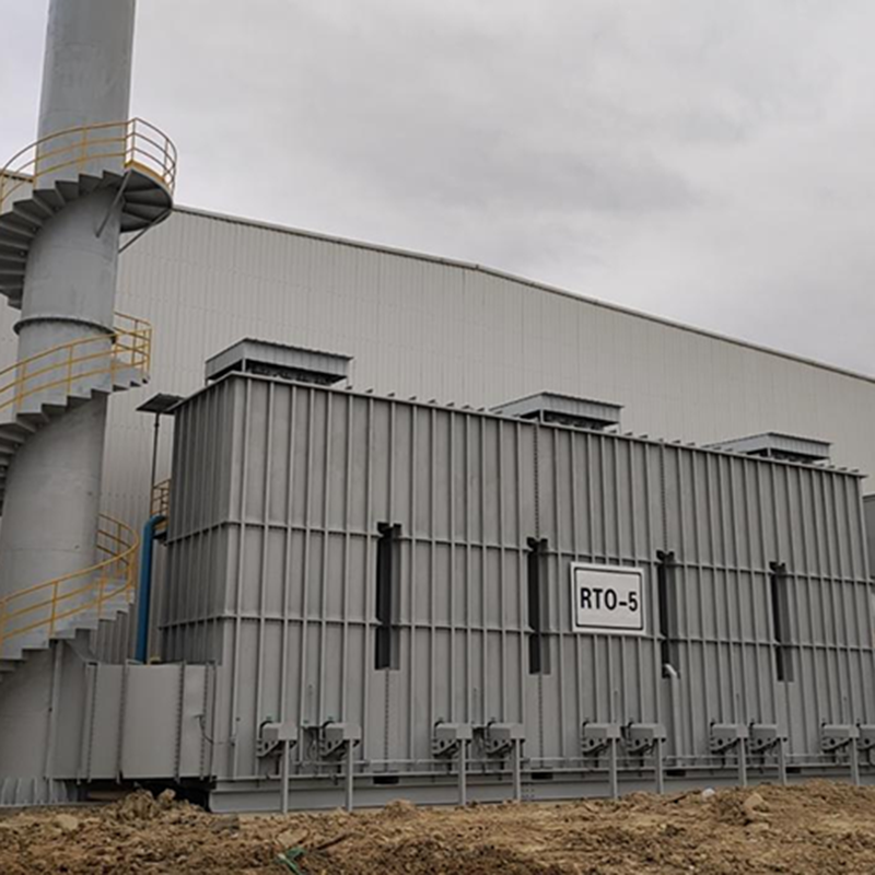 LQ-RTO Heat-storage high-temperature incineration equipmentApplicable Industries And RangeView Product →
Where the coating room and general ventilation have to be treated as well, the volume changes the picture completely. A zeolite rotary concentrator removes the solvent from 25,000 cubic metres an hour of dilute air and delivers it into roughly 2,000 cubic metres an hour of concentrated air, which is then destroyed in a comparatively small oxidizer. The combination reduces the size of the combustion equipment by an order of magnitude and is often the only way to bring a large coating room into compliance without an unreasonable gas bill.
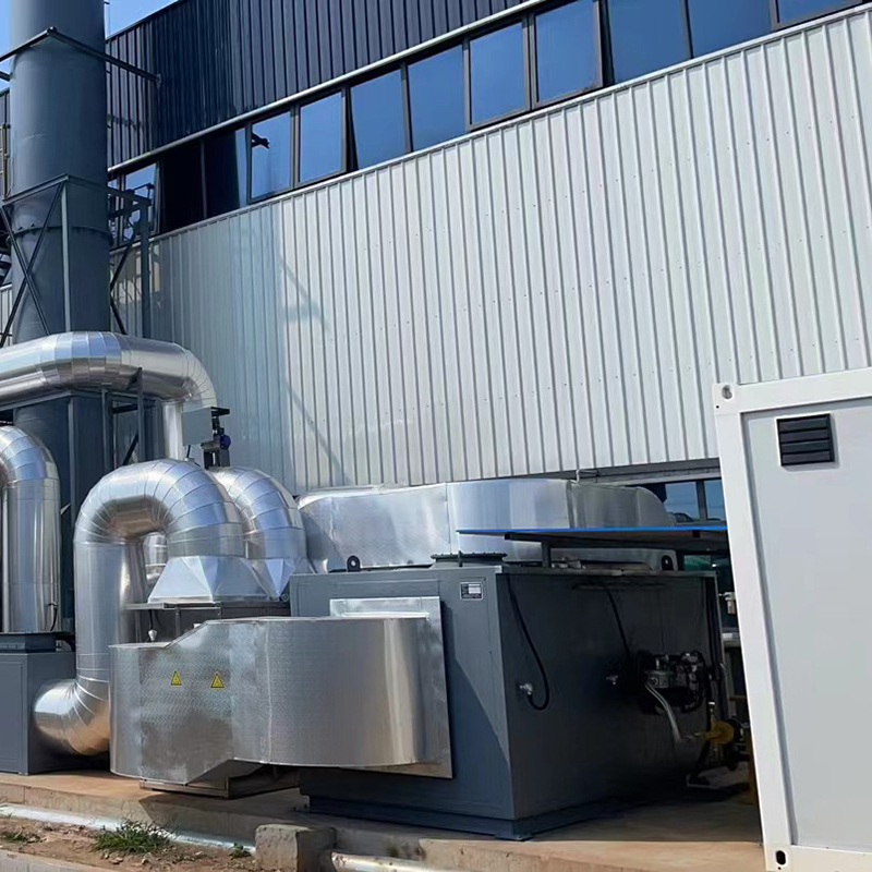 LQ-ADW-RTO Zeolite Rotary Concentrator (Cylindrical/Disc Type)+Regenerative Thermal OxidizAir containing VOCs to be treated is sent to the treatment area of the concentrated zeolite rotary drum after pre-filtration. In the treatment area, VOCs are removed b...View Product →
Catalytic oxidation has a place in fastener plants, but a narrow one. It suits clean streams from adhesive curing, printing or marking operations where the exhaust carries no silicon, no phosphorus and no metal-bearing particulate. Putting a catalytic oxidizer behind a zinc-flake curing oven is a reliable way to spend money on catalyst replacement every eighteen months.
Treat the concentrated oven stream directly with RTO, and concentrate the dilute room stream before oxidation; catalytic media should never see zinc-flake oven exhaust.
Two oxidizers with identical flow ratings and identical destruction efficiency claims can behave completely differently after three years. The difference lies in a handful of specification decisions that are easy to overlook in a quotation comparison.
Structured ceramic monolith blocks give lower pressure drop and are easier to inspect than randomly packed saddles, but they are more sensitive to particulate bridging in narrow channels. Random packing tolerates dust better but carries a higher fan energy penalty. For coating oven exhaust, structured media with channel widths of four millimetres or greater is a reasonable compromise for the hot side, with wider channels on the cold inlet side.
Poppet valves and rotary distributors both work; the choice usually follows flow rate and maintenance philosophy. What matters more is the switching interval. Longer intervals reduce valve wear but increase the temperature swing at the outlet and therefore the emission spike on each switch. For odour-sensitive sites, a three-canister arrangement with a purge cycle is worth the additional cost.
The combustion chamber shell should be lined with ceramic fibre modules rated well above the operating temperature, with a hot-face grade that resists the trace acid species present in coating exhaust. Cold-side steelwork in contact with condensate should be stainless or coated, and the stack should be designed for condensate drainage, not just gas flow. Insulation thickness on ductwork carrying saturated gas is a cost decision that quickly becomes a corrosion decision.
The safety package on a fastener coating oxidizer is not optional equipment, it is the equipment. A typical specification includes continuous lower-explosive-limit monitoring at the inlet with a fast-response sensor and a high-high trip, a dilution air damper, a high-temperature bypass, flame detection on the burner, a gas train with double block and bleed, pressure and flow interlocks on the combustion air fan, and an emergency stop that also handles the process oven.
One design habit worth insisting on is trend logging rather than alarm-only monitoring. Media plugging, valve leakage and burner degradation all develop slowly, and a plant that can see a pressure drop rising from 1.8 to 2.6 kilopascals over four months has time to plan a shutdown. A plant that only sees a high-high alarm has a forced outage instead.
Specify trend logging, differential pressure transmitters and lower-explosive-limit monitoring as standard; they turn a forced outage into a planned one.
The operating cost of a regenerative thermal oxidizer is dominated by two variables: how much heat the ceramic media recovers, and how much solvent the stream brings in as free fuel. Everything else, including fan power and instrument air, is a rounding error by comparison.
At 95 percent heat recovery, field experience places the autothermal point somewhere around 1,500 to 2,000 milligrams per cubic metre of solvent in the incoming stream, depending on the solvent's calorific value and the heat losses of the particular unit. Dip-spin curing ovens comfortably exceed this during the curing phase. Between batches, when the oven is at temperature but no parts are passing through, the concentration falls away and supplementary gas takes over.
That batch behaviour drives three specification decisions. First, a properly sized turndown ratio on the burner, because a burner that cannot modulate below 30 percent of its rated firing rate will cycle on and off and lose efficiency. Second, variable-frequency drives on the process fan, so that flow can be reduced during idle periods without losing capture at the oven. Third, a genuine idle mode that keeps the chamber above the solvent auto-ignition margin while minimising gas input, rather than a full-flow, full-temperature standby.
Shift patterns matter as much as equipment. A plant running three shifts and a full coating schedule will see the oxidizer autothermal for most of the week. A plant running one shift, five days a week, spends a large fraction of its operating hours paying for gas rather than destroying solvent, and in that case the concentrator plus oxidizer route or a smaller unit with a heat recovery upgrade usually pays back faster than a larger direct oxidizer.
Recovered heat is the other lever. Hot air from the oxidizer outlet can be routed back to the curing oven as preheated combustion air or makeup air, cutting the oven's own gas consumption. This heat integration is often overlooked and can be worth more than a marginal improvement in oxidizer heat recovery. It does require the oven and the oxidizer to be designed as one system rather than two purchases, which is an argument for buying them from the same engineering supplier.
Finally, maintenance cost should be modelled as a function of hours, not years. Media replacement, valve seal kits, burner components, thermocouples, lower-explosive-limit sensors and fan bearings all have different service lives, and a plant that sets aside media replacement at around 20,000 operating hours will not be surprised.
Batch curing means turndown, idle mode and heat integration decide the gas bill, not the nominal heat recovery percentage in the brochure.
Fastener manufacturers in China answer to a layered set of requirements: the integrated emission standard for air pollutants, the volatile organic compound emission standard for industries without a dedicated standard, and, where they exist, stricter provincial or municipal limits. Provinces along the eastern seaboard apply markedly tighter non-methane hydrocarbon limits to coating and surface treatment than the national baseline, and industrial parks frequently add their own requirements on top.
Two practical points follow. The first is that the compliance target should be written into the equipment contract as a performance guarantee tied to a stack test, not as a bare destruction efficiency figure. A guaranteed 99 percent destruction on a balanced stream means nothing if the balanced duct does not capture the fugitive emissions that dominate the fence-line measurement.
The second is odour. A plant can be fully compliant on mass concentration and still receive complaints, because some solvent species and oxidation by-products are detectable at concentrations far below any regulatory threshold. Fastener coating lines using mixed solvents are particularly prone to this, and the answer is usually a higher oxidation temperature, a longer residence time, or a purge-equipped three-canister configuration rather than a different technology.
Testing itself should be planned from the start. The design should include a properly located sampling port with safe access, downstream of the oxidizer and far enough from the outlet to allow complete mixing, with a platform that a third-party testing team will actually accept. Retrofitting a compliant sampling location onto a finished stack costs more than anyone expects.
For plants that export fasteners to European or North American customers, the emission data will increasingly be requested as part of supplier audits and product carbon declarations. Keeping twelve months of continuous monitoring records, maintenance logs and media replacement history in a retrievable format is no longer an administrative nicety; it is part of the commercial relationship.
Write the performance guarantee against a stack test at the actual stack, and design the sampling port and platform before the equipment is fabricated.
The market for VOCs abatement equipment includes specialist manufacturers, general engineering integrators and trading companies that resell imported components. For a fastener coating application, where pre-treatment design and system integration matter more than the burner, the distinction is significant.
A specialist manufacturer designs the oxidizer, the heat recovery media, the ductwork, the pre-treatment stages and the controls as one system, and takes responsibility for the stack test. An integrator assembles purchased components and typically excludes performance risk from the contract. Both can deliver a working system, but the risk profile is different, and the difference shows up in the first eighteen months of operation.
Ask for the control philosophy document, not just a piping and instrumentation diagram. Ask which media grade is proposed and why, and how the supplier's design accounts for the silicon and phosphorus content of the specific lubricants and coatings used on site. Ask what happens to the warranty if media plugging occurs within the first two years, and get the answer in writing.
A manufacturer with a long track record in organic waste gas treatment, a defined fabrication base and verifiable certifications is a safer counterparty than the lowest bidder with an impressive brochure. Certificates held by the supplier, covering both design and construction scope, provide a documentary basis for the technical review that a purchasing department can actually use.
The company behind this site, for example, holds dual-grade design and treatment qualifications for environmental pollution in Jiangsu Province together with an environmental engineering contracting grade, ISO 9001 and ISO 14001 registration, and 13 utility model patents plus two invention certificates. Those documents, and the certificate records behind them, are the kind of evidence worth requesting from any supplier before an order is placed.
Buy the pre-treatment design, the controls and the performance guarantee together with the oxidizer, from one accountable manufacturer.
Maintenance on a coating-line oxidizer is mostly about watching trends and cleaning things before they become expensive. The schedule below reflects what actually consumes time and money in fastener plants.
Scheduling matters as much as method. In many plants the adsorbent media upstream of the oxidizer is replaced on a calendar basis long after it has stopped working, while the oxidizer media is inspected only when a fault appears. Aligning both routines to actual measured performance, rather than to a fixed date, avoids both unnecessary spending and unexpected loss of efficiency.
Related reading from our technical library
When and why the adsorbent in front of an oxidation system needs replacing
Track differential pressure across the media bed weekly; it is the earliest and cheapest indicator that something upstream has stopped working.
Size on the curing oven exhaust first, because that is the concentrated stream. A medium dip-spin line typically produces 1,500 to 4,000 cubic metres an hour from the oven at 1,200 to 3,000 milligrams per cubic metre, which suits a compact two- or three-canister unit. If coating room and general ventilation must also be treated, that volume is handled separately, usually through a concentrator, rather than added to the oxidizer inlet.
Not directly, and not economically. Quench and temper exhaust is dominated by condensable oil mist with a comparatively small VOC fraction. An electrostatic precipitator or wet scrubber should remove the oil mist, and if cracked organics still need oxidation afterwards, a small oxidizer can be considered. Sending oil mist straight to ceramic media guarantees plugging.
Because coating exhaust carries three things printing exhaust usually does not: fine metallic coating solids, silicone-bearing lubricant residues that fuse into glass at combustion temperature, and high-boiling glycol ethers that condense on the cold side. Pre-filtration and source substitution matter more here than media selection.
No. It becomes worthwhile when the stream is large and dilute, typically above 15,000 cubic metres an hour with concentrations below 300 milligrams per cubic metre. Below those figures the concentrator's own cost, power consumption and maintenance usually outweigh the savings on oxidizer size.
For hydrocarbon solvents typical of fastener coatings, 760 to 850 degrees Celsius with adequate residence time is standard practice. If halogenated solvents are present anywhere in the process, the chamber must run hotter and the downstream section must be built from corrosion-resistant material with a quench or heat exchanger to protect the stack.
During curing, with concentration above the autothermal point and heat recovery at 95 percent, the answer can be close to zero. Between batches and during idle periods, consumption rises. The annual figure depends far more on shift patterns and on whether the burner has real turndown and an idle mode than on the nominal efficiency figure.
Yes, but the economics change. A single-shift plant pays for warm-up and standby every day, so a smaller oxidizer with a well-integrated heat recovery loop, or a concentrator-based system that runs only during production, often gives a better return than a large direct oxidizer.
Catalytic oxidation is suitable for clean streams with no silicon, phosphorus, sulphur or heavy metals. Zinc-flake coating oven exhaust contains all of those risks to some degree, so RTO is the safer choice for coating lines. Catalytic units remain useful on adhesive curing, marking and printing exhausts where the stream is genuinely clean.
Continuous monitoring of chamber temperature, media differential pressure and valve performance, combined with periodic portable analyser checks at the outlet, gives a reliable picture. Trend data recorded over twelve months is also what customer audits and carbon reporting requests will ask for.
Buying it as a standalone box rather than as part of a system. The capture hood, the duct layout, the pre-treatment stage, the control philosophy and the heat integration all determine whether the oxidizer performs. A perfectly built oxidizer behind a badly designed capture and duct system will fail its stack test every time.
Most RTO problems in fastener plants are capture, ducting and pre-treatment problems that only appear when the stack is tested.
Bring the discussion back to where it started. The curing oven on a dip-spin line is hot, concentrated and batch-driven, and it is the stream that a regenerative thermal oxidizer was designed for. The coating room around it is large, dilute and easy to underestimate. Separating those two streams, characterising them properly, protecting the ceramic media from solids, silicon and sticky condensate, and specifying turndown and trend logging rather than chasing a headline efficiency number is what separates a system that runs quietly for a decade from one that is replaced in three years.
For fastener manufacturers, the practical sequence is straightforward. Measure the streams before accepting any quotation. Segregate the concentrated and dilute exhausts at the drawing stage. Select pre-treatment that removes what combustion cannot handle. Match the oxidation platform to the measured concentration and flow, not to a template. Insist on a performance guarantee tied to a stack test, and on documentation that a purchasing department can verify.
Done in that order, a regenerative thermal oxidizer becomes one of the least troublesome pieces of equipment in the plant. Done in the reverse order, it becomes the piece everyone talks about, and never in a good way.
Measure first, separate the streams, pre-treat properly, then buy an oxidizer designed around those numbers rather than around a template.
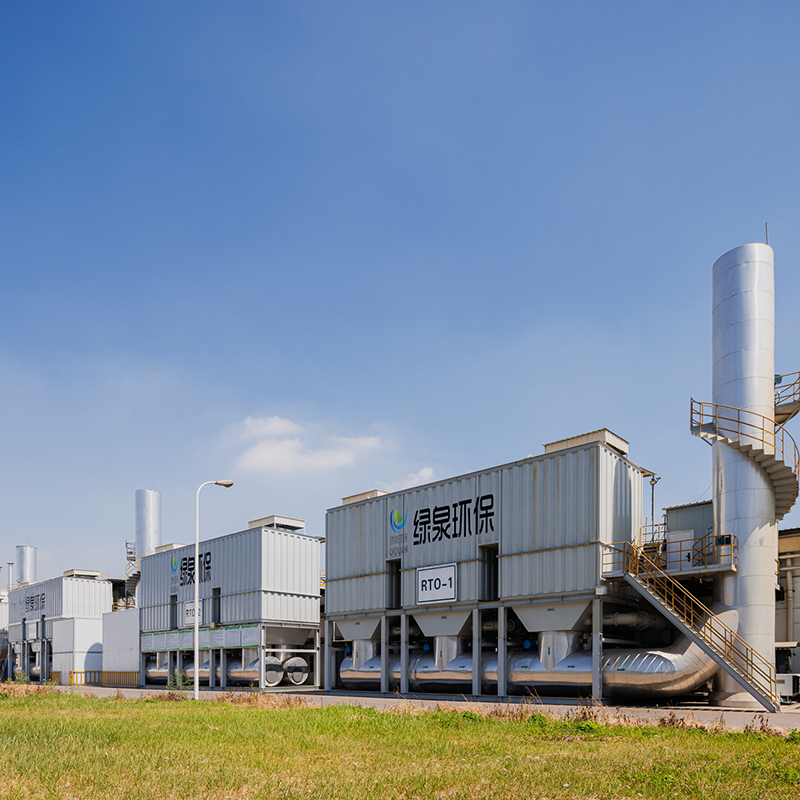
Overview Of Tower-Type RTO Regenerative Thermal Oxidizer (RTO) is an organic waste gas treatment equipment that combines high-temperature oxidation wi...
See Details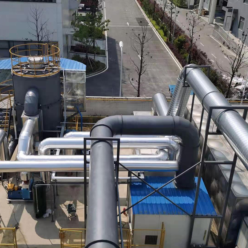
Overview Of Tower-Type RTO Our company offers two types of rotary RTO, which are the rotary RTO and the single barrel multi-valve RTO. The rotary RTO,...
See Details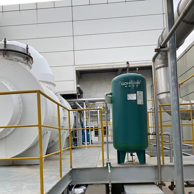
Overview Direct combustion high-temperature incineration equipment, abbreviated as TO, utilizes the heat generated by the combustion of auxiliary fuel...
See Details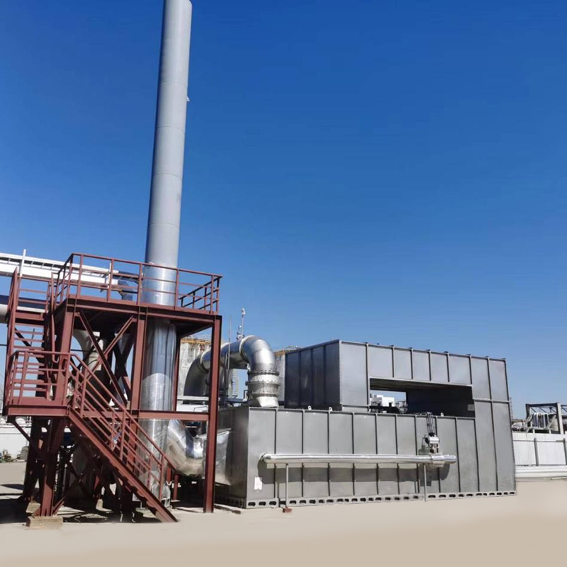
Overview Catalytic combustion is a purification method that uses catalysts to oxidize and decompose combustible substances in exhaust gas at low tempe...
See Details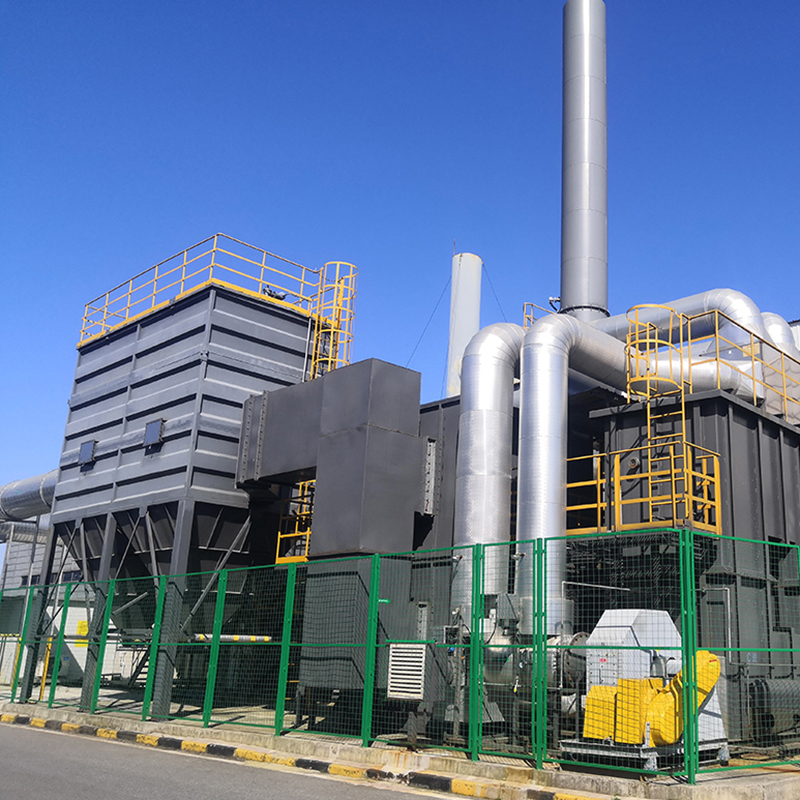
Concept Of Zeolite Wheel+RTO System Using zeolite wheel to adsorb organic waste gas, the low concentration and high air volume waste gas is concentrat...
See Details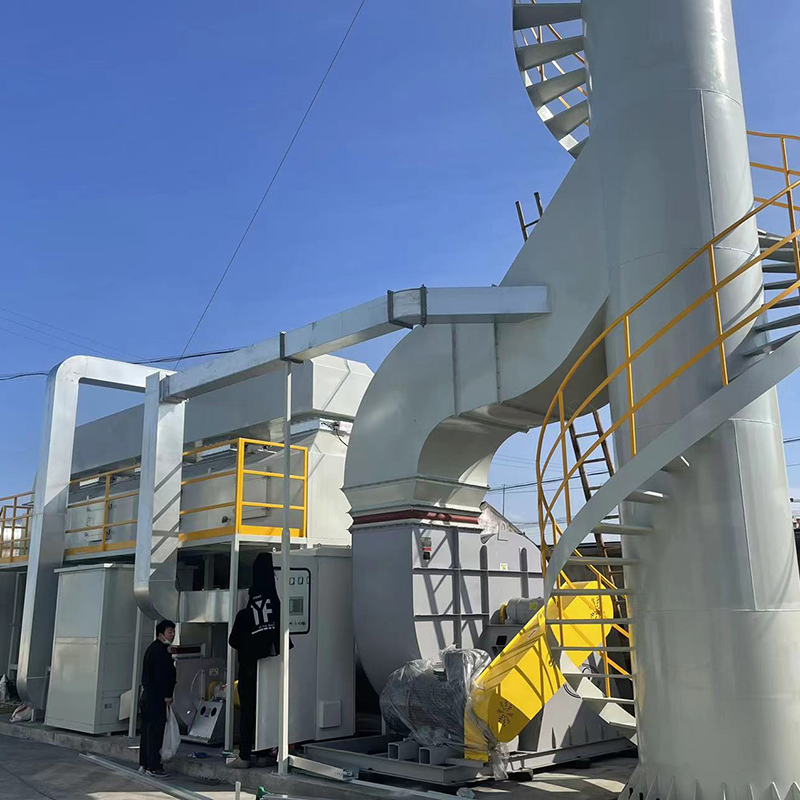
The VOC-CFT-CO Adsorption Catalytic Purification Equipment The VOC-CFT-CO adsorption catalytic purification equipment, consisting of fixed-bed honeyco...
See Details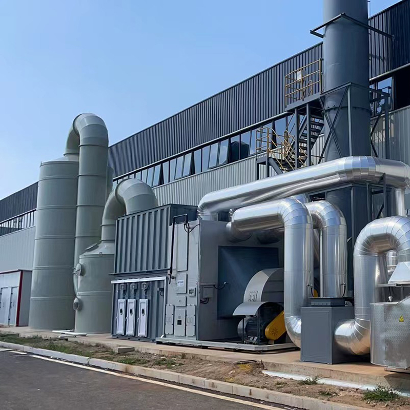
Concept Of Fixed Bed Zeolite + Catalytic Combustion As A Set Of Equipment The fixed bed zeolite + catalytic combustion device is suitable for the conc...
See Details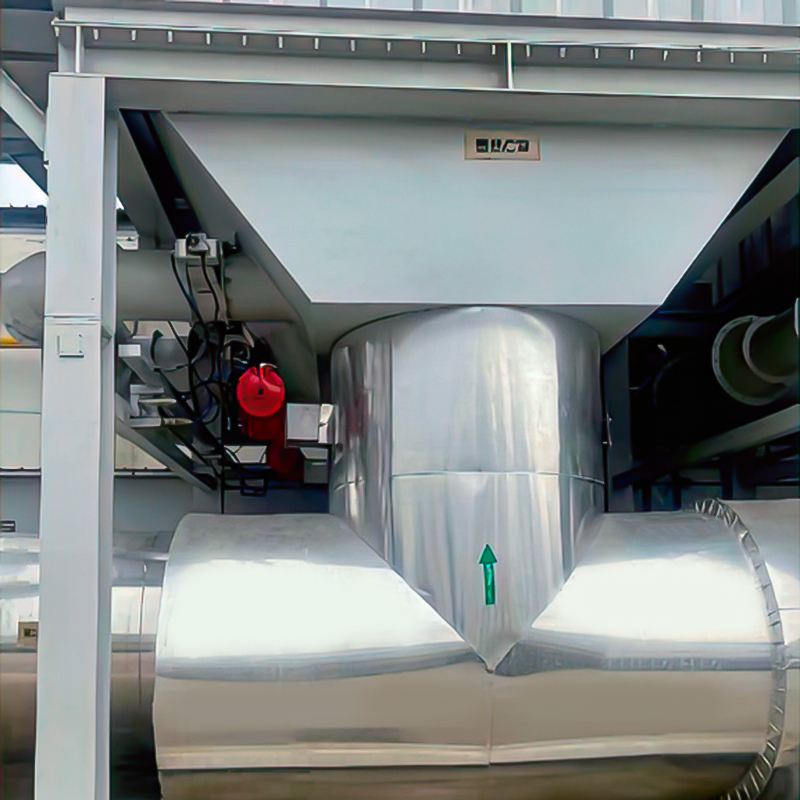
Purpose Mainly used for proportional ventilation of high-temperature flue gas. lt is widely used in places where leak rate requirements are not high, ...
See Details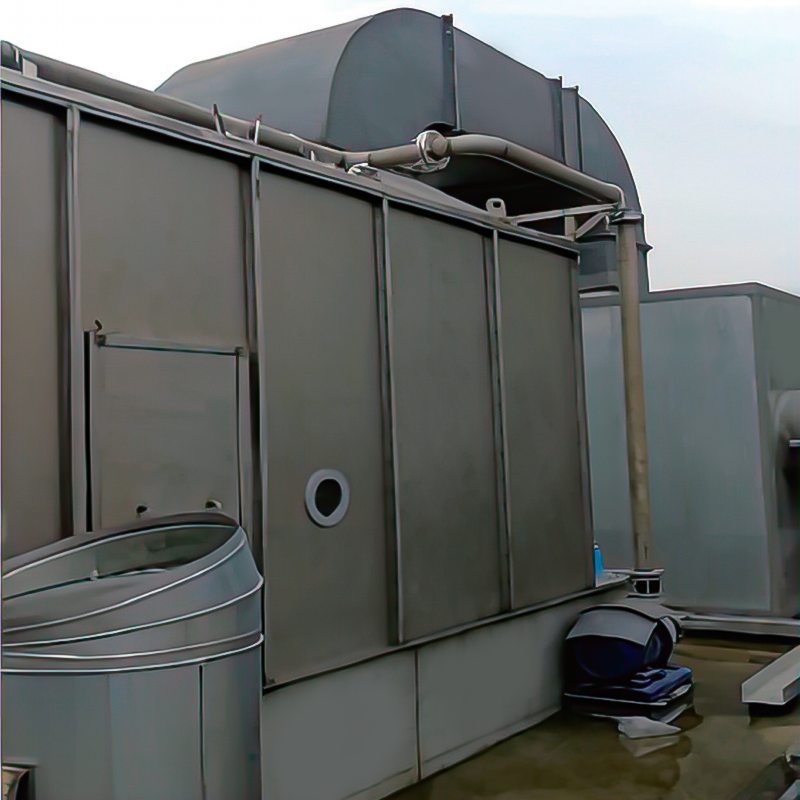
Overview The wet dust removal principle uses the process of capturing and separating dust particles in the gas phase by fully contacting gas-liquid tw...
See Details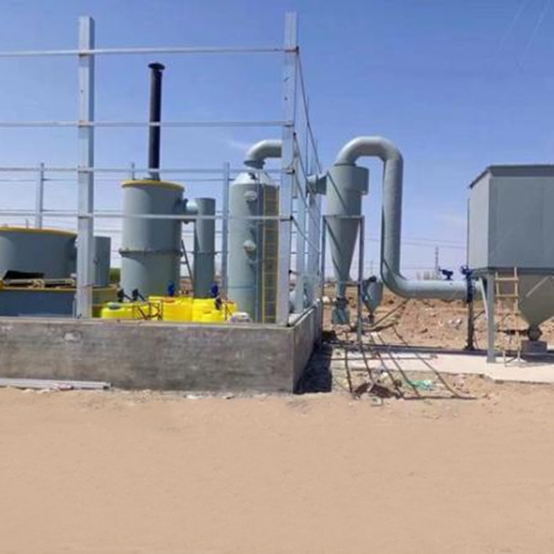
Overview Solid waste incineration furnaces are essential equipment in the management of solid waste, designed to transform waste materials into ash an...
See DetailsMOBILE
Product Manual

Copyright © Lv quan Environmental Protection Engineering Technology Co., Ltd. All Rights Reserved. Vocs Organic Waste Gas Treatment Engineering Equipment Manufacturer

