 English
 русский
 Français
 Español
 عربى
عربىLQ-RTO Heat-storage high-temperature incineration equipment
Cat:Equipment
Overview Of Tower-Type RTO Regenerative Thermal Oxidizer (RTO) is an organic waste gas treatment equipment that combines high-temperature oxidation wi...
See Details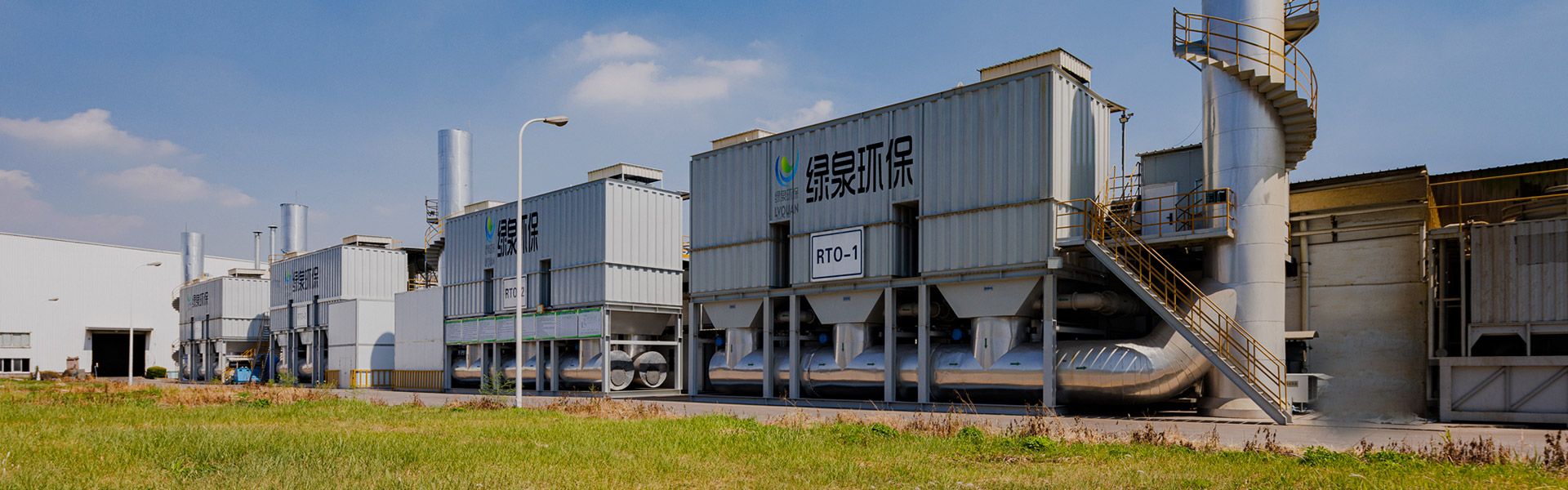
Content
The direct answer is that VOCs organic waste gas treatment engineering equipment accessories are used to protect, support, and optimize the performance of the core treatment units within an industrial VOCs waste gas treatment system. Components such as high temperature pressure relief valves and horizontal spray cabinets are not the primary purification unit itself, but they perform critical supporting functions including overpressure protection, particulate pretreatment, temperature control, and airflow direction within the overall exhaust gas treatment equipment chain. Without properly matched accessories, even a well designed activated carbon VOCs system or catalytic oxidation VOCs system can suffer from unstable airflow, premature equipment wear, or unsafe pressure buildup during process fluctuations. This is why engineering firms specializing in organic waste gas treatment, such as Lvquan Environmental Protection Engineering Technology Co., Ltd., design accessories as an integrated part of the full VOCs air treatment system rather than as an afterthought. The sections below walk through how these systems work, how different treatment technologies compare, what specific accessories do within the system, and how to select the right configuration for a given industrial application.
A typical industrial VOCs waste gas treatment system follows a general sequence that begins with capture, moves through pretreatment, continues into a core purification stage, and ends with safe discharge through a stack. Exhaust gas containing volatile organic compounds is first collected through capture hoods or ductwork positioned near the emission source, such as a painting workshop exhaust treatment line or a printing industry VOCs control point. The collected gas then commonly passes through a pretreatment stage, where a horizontal spray cabinet can remove particulates, cool the gas stream, or in some fire protection configurations assist with rapid area coverage for safety purposes. After pretreatment, the gas enters the core treatment unit, which may rely on adsorption using activated carbon, catalytic oxidation, or thermal oxidation depending on the concentration and composition of the VOCs present. Safety and control accessories, including pressure relief valves rated for high temperature service, are positioned at key points in the ductwork to protect the system from overpressure events before the treated gas is released as clean exhaust.
Choosing between activated carbon vs catalytic oxidation is one of the most common early decisions in designing a VOCs air treatment system, and the right choice depends heavily on gas concentration, flow rate, and the specific compounds involved. Activated carbon VOCs systems work through adsorption, where organic molecules are captured on the porous surface of carbon media, and this approach is generally well suited to lower concentration streams with intermittent flow. Catalytic oxidation VOCs systems instead convert organic compounds into carbon dioxide and water vapor through a controlled oxidation reaction over a catalyst bed, which tends to perform well on more continuous, moderate concentration gas streams. General industrial air pollution control references, including technology overview material published by the U.S. Environmental Protection Agency on VOC control technologies, describe both adsorption and oxidation as established approaches with different operating ranges rather than one being universally superior. The chart below presents an illustrative comparison of typical removal efficiency ranges reported across general industry technology descriptions, rather than certified test data for any single specific installation.
The horizontal bar chart above shows a general pattern in typical removal efficiency ranges across four common approaches to industrial exhaust gas treatment, and it is intended as an illustrative reference rather than a certified measurement for any one facility. Simple ventilation without a dedicated treatment stage offers the lowest relative performance, since it primarily dilutes rather than actively removes organic compounds from the airstream. Activated carbon adsorption and catalytic oxidation both show meaningfully stronger performance, which is consistent with why these two technologies remain the most widely referenced options in industrial VOCs purification system design. A combined multi-stage system, which pairs pretreatment accessories such as a spray cabinet with a core adsorption or oxidation unit, tends to show the strongest overall pattern because each stage addresses a different part of the gas stream, from particulates and temperature to the organic compounds themselves. This general pattern supports the broader engineering principle that VOCs treatment equipment accessories, while not the primary purification technology, materially affect the overall performance of the system they support.
For facilities evaluating an RTO vs RCO system, the core difference lies in how each technology manages heat during the oxidation process, which directly affects energy efficiency and suitability for different concentration ranges. A regenerative thermal oxidizer, commonly referred to as RTO, uses ceramic heat exchange media to recover a large portion of the thermal energy generated during oxidation, which makes it well suited to facilities with moderate to high VOC loading where energy recovery has a meaningful impact on operating efficiency. A regenerative catalytic oxidizer, or RCO, achieves oxidation at a lower operating temperature by relying on a catalyst, which can reduce fuel consumption for lower concentration streams but generally requires more attention to catalyst condition over time. The radar chart below compares RTO, RCO, and activated carbon adsorption across several qualitative dimensions relevant to selecting a VOCs treatment equipment configuration, and it should be read as a general planning comparison rather than a precise laboratory benchmark.
The radar chart above compares three common industrial VOCs treatment approaches across six qualitative planning dimensions, and it is meant to support technology selection discussions rather than replace a site specific engineering evaluation. RTO systems score highest on energy recovery and continuous duty fit, which reflects their heat exchange design and their common use in facilities running long, steady production shifts such as coating factory air purification lines. RCO systems sit in a middle position, offering reasonable performance across most dimensions while generally requiring lower operating temperatures than RTO, which can be an advantage for facilities focused on moderate energy input. Activated carbon adsorption scores highest on startup flexibility and low concentration fit, since carbon beds can be brought online quickly and perform well when VOC loading is lower or intermittent, such as smaller printing industry VOCs control applications. Understanding these relative strengths helps engineering teams and facility managers narrow down the right core technology before finalizing the surrounding VOCs treatment equipment accessories that support it.
Beyond the core adsorption or oxidation unit, a complete VOCs organic waste gas treatment engineering equipment package relies on a set of supporting accessories that each perform a specific function within the system. Lvquan Environmental Protection Engineering Technology Co., Ltd. produces a range of these VOCs system components, two of which are described below along with their role in a typical industrial exhaust gas treatment equipment layout.

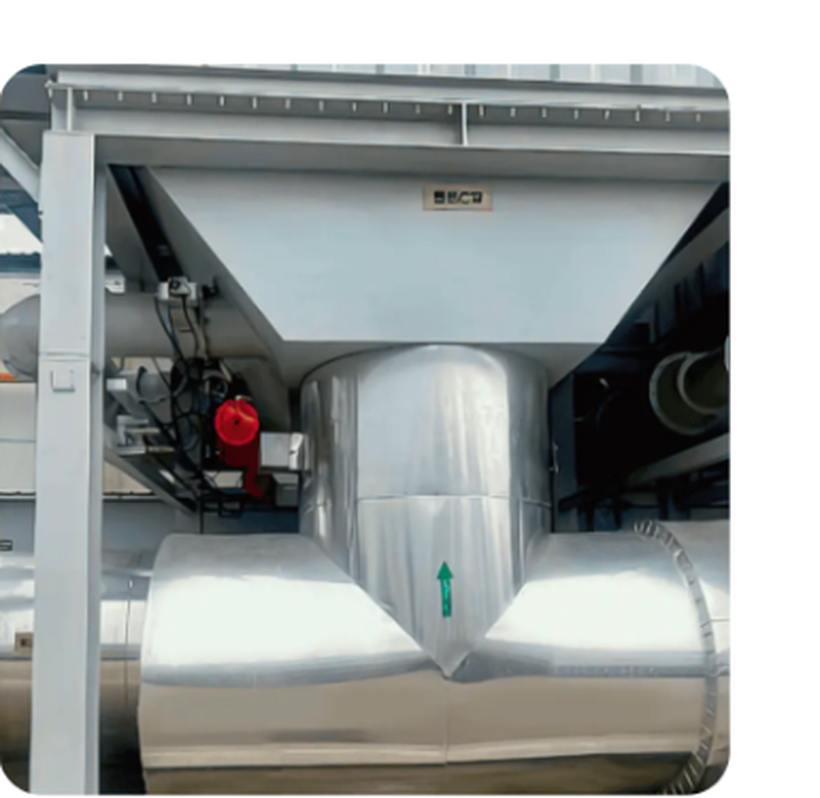
The LQ-WPG horizontal spray cabinet uses an efficient spray system combined with an optimized internal space layout to achieve full coverage of the gas stream in a short residence time. This design allows the unit to effectively remove harmful particulates from the air stream before it reaches downstream treatment stages, which reduces particulate loading on activated carbon beds or catalyst surfaces further along the system. In configurations focused on fire protection and area cooling, the same horizontal spray principle supports rapid coverage across a protected space, which is why this accessory type is well suited to environments such as data centers, warehouses, and production workshops that require both efficient daily cleaning support and dependable fire protection response. Positioning a spray cabinet as a pretreatment stage ahead of a core VOCs purification unit is a common waste gas scrubber system parts strategy, since it helps protect more sensitive downstream components from particulate fouling. This structural role is one of the reasons pretreatment accessories are considered an integral part of gas treatment accessories planning rather than an optional add on.
The LQ-GXF high temperature pressure relief valve is constructed from high temperature resistant materials and combined with precise sealing technology, allowing it to operate stably under demanding high heat process conditions. Its primary function is to prevent overpressure events within ductwork and process piping, opening in a controlled manner to release excess pressure before it can damage upstream equipment or compromise system safety. This type of accessory is widely used in high temperature process pipelines across petrochemical facilities, power stations, and metallurgy plants, where sudden pressure spikes can occur during process upsets or equipment transitions. Within a VOCs waste gas treatment system that includes thermal oxidation stages, a properly rated pressure relief valve is a critical exhaust system parts component, since combustion based treatment methods can generate localized pressure and temperature fluctuations that need to be safely managed. Selecting a pressure relief valve rated for the correct temperature and pressure range is one of the most important engineering decisions in protecting the long term integrity of an industrial VOCs control system.
The simplified flow diagram above illustrates the general sequence in which VOCs treatment equipment accessories connect within a complete organic waste gas treatment system, and it is intended as a conceptual layout rather than an exact piping and instrumentation drawing for any specific project. Gas enters through a capture hood or duct network, moves into a pretreatment stage such as a horizontal spray cabinet, then proceeds into the core treatment unit where the majority of VOCs removal occurs through adsorption or oxidation. A pressure relief valve is positioned near the downstream end of the system, where it stands ready to respond to any overpressure condition before treated gas reaches the exhaust stack. This staged approach reflects standard waste gas treatment engineering design guide practice, where each accessory addresses a specific risk or performance factor rather than a single unit attempting to manage every function at once. Facilities planning a new industrial VOCs purification system, or upgrading an existing one, generally benefit from reviewing this full sequence with an experienced engineering partner rather than selecting individual components in isolation.
Demand for VOCs treatment equipment accessories spans a range of industrial sectors, and the specific accessory configuration often shifts depending on the source of the organic waste gas. Painting workshop exhaust treatment applications typically generate particulate laden gas streams that benefit from a spray cabinet pretreatment stage ahead of a core adsorption or oxidation unit. Printing industry VOCs control often deals with more consistent solvent based emissions, which tends to favor a stable core treatment technology paired with accessories that support continuous operation. Chemical plant VOCs treatment and metallurgy applications frequently involve higher temperature process conditions, which is where high temperature resistant pressure relief valves become especially important for protecting piping integrity. The donut chart below presents a general illustrative distribution of accessory demand across these industry categories, based on common patterns described in industrial air pollution control literature rather than an exact measured market survey.
The donut chart above illustrates a general pattern of where VOCs treatment equipment accessories tend to be applied across four broad industry categories, and it should be read as a directional reference rather than a precise measured market breakdown. Painting workshops represent a meaningfully large share of typical demand, largely because coating and spraying processes generate both particulate matter and organic solvent vapor that require a combined pretreatment and core treatment approach. Printing industry applications also make up a significant portion, reflecting the widespread use of solvent based inks and coatings across packaging and publication printing operations. Chemical plants and metallurgy or other high temperature industrial processes make up a smaller but still important share, and these applications tend to place greater emphasis on high temperature resistant accessories such as pressure relief valves rather than particulate focused pretreatment. This general distribution pattern is useful context for facility managers benchmarking their own VOCs air treatment system needs against how similar accessories are used across comparable industrial settings.
Understanding how VOCs are removed at each stage of the system helps explain why accessories matter even when they are not the primary purification technology. The area chart below presents an illustrative view of cumulative removal efficiency as gas moves through a typical four stage industrial VOCs purification system, based on general engineering process logic rather than certified test data for a specific installation.
The area chart above shows a general upward pattern in cumulative removal efficiency as gas moves through the four broad stages of a typical industrial waste gas treatment engineering process, from initial capture through to final discharge. The capture stage alone contributes only modest removal, since its main function is collecting the gas stream rather than actively treating it. The pretreatment stage, which can include a horizontal spray cabinet, adds a further increase by removing particulates and stabilizing temperature ahead of the core treatment unit. The steepest gain occurs during the core treatment stage, where activated carbon adsorption or catalytic oxidation performs the majority of organic compound removal, which is consistent with why this stage is generally considered the primary VOCs treatment equipment investment. The gradual leveling near final discharge reflects diminishing incremental gains once the core treatment has already addressed most of the VOC load, reinforcing the practical takeaway that pretreatment and safety accessories exist to protect and stabilize the system rather than to independently drive the largest efficiency gains.
Selecting the right combination of core treatment technology and supporting accessories becomes easier with a structured checklist, particularly for facility managers comparing options for the first time.
| Accessory Type | Primary Function | Typical Placement |
|---|---|---|
| Horizontal Spray Cabinet | Particulate removal, gas cooling, fire protection coverage | Pretreatment stage, ahead of core unit |
| High Temperature Pressure Relief Valve | Overpressure protection, system safety | Downstream ductwork and process piping |
| Ducting and Capture Hoods | Gas collection and routing | Emission source to pretreatment stage |
| Core Adsorption or Oxidation Unit | Primary VOCs removal | Central treatment stage |
Consistent maintenance keeps a VOCs waste gas treatment system operating reliably and helps extend the working life of both the core treatment unit and its supporting accessories.
Following a structured VOCs treatment system maintenance guide reduces the likelihood of unplanned downtime and supports consistent compliance with air pollution control requirements over the operating life of the equipment. Facilities working with an established VOCs equipment parts supplier generally find it easier to source replacement accessories quickly when routine inspection identifies a component nearing the end of its service interval.
Lvquan Environmental Protection Engineering Technology Co., Ltd. is located in Gaoyou, Yangzhou, an area often described as the north gate of Jiangsu province, and operates as a joint stock enterprise formed through the cooperation of professionals with more than thirty years of combined experience in VOCs equipment design and manufacturing. As a professional VOCs organic waste gas treatment engineering equipment manufacturer, the company maintains a registered capital of twenty two million yuan, fixed assets of nearly forty million yuan, and total assets of nearly sixty million yuan, supporting a factory building area of nine thousand eight hundred square meters. The company operates more than two hundred sets of various types of machining equipment and employs one hundred twenty staff members, supporting an annual production capacity of one hundred million yuan across its VOCs treatment equipment accessories and full engineering equipment product lines. This combination of engineering experience, manufacturing scale, and dedicated production capacity supports the company's role as a China VOCs treatment equipment factory serving customers in need of custom VOCs waste gas treatment systems, OEM VOCs treatment system projects, and turnkey VOCs treatment solution delivery for a wide range of industrial applications.
Q1: What are VOCs organic waste gas treatment equipment accessories used for?
These accessories support the core treatment unit by handling functions such as particulate pretreatment, gas cooling, and overpressure protection, which together help the overall VOCs waste gas treatment system operate safely and consistently.
Q2: What is the difference between activated carbon and catalytic oxidation for VOCs treatment?
Activated carbon systems remove organic compounds through adsorption onto porous carbon media, while catalytic oxidation converts organic compounds into carbon dioxide and water vapor through a controlled reaction over a catalyst.
Q3: How does an RTO system differ from an RCO system?
An RTO system uses ceramic heat exchange media to recover thermal energy during oxidation, while an RCO system relies on a catalyst to achieve oxidation at a lower operating temperature.
Q4: What is a high temperature pressure relief valve used for in a VOCs system?
It is used to release excess pressure in a controlled manner during process upsets, protecting ductwork and process piping from overpressure damage in high temperature applications such as thermal oxidation.
Q5: Can VOCs treatment equipment accessories be customized for a specific facility?
Yes, many manufacturers offer custom VOCs waste gas treatment system configurations, allowing accessories such as spray cabinets and pressure relief valves to be matched to specific process conditions and industry requirements.
Q6: How often should a VOCs waste gas treatment system be inspected?
Inspection frequency depends on process conditions, but routine checks of spray cabinets, pressure relief valves, carbon beds, and catalyst condition are generally recommended as part of standard maintenance planning.

Overview Of Tower-Type RTO Regenerative Thermal Oxidizer (RTO) is an organic waste gas treatment equipment that combines high-temperature oxidation wi...
See Details
Overview Of Tower-Type RTO Our company offers two types of rotary RTO, which are the rotary RTO and the single barrel multi-valve RTO. The rotary RTO,...
See Details")
Overview Direct combustion high-temperature incineration equipment, abbreviated as TO, utilizes the heat generated by the combustion of auxiliary fuel...
See Details
Overview Catalytic combustion is a purification method that uses catalysts to oxidize and decompose combustible substances in exhaust gas at low tempe...
See Details
Overview Thermal storage catalytic oxidation (Regenerative Catalytic Oxidizer/RCO) is an organic waste gas treatment equipment that combines low-tempe...
See Details")
Overview Of Variable Freouency Zeolite Turntable Our company's zeolite concentration turntable uses a combination of zeolite modules, with a high zeol...
See Details
Product Introduction Gas heat exchanger is mainly used for energy saving and emission reduction industries in the waste heat recovery of flue gas in v...
See Details+ Catalytic Oxidation (CO)")
Concept Of Zeolite Rotary Wheel + Catalytic Combustion As A Set Of Equipment In the combined process of organic waste gas and waste gas treatment, the...
See Details
Purpose Mainly used for proportional ventilation of high-temperature flue gas. lt is widely used in places where leak rate requirements are not high, ...
See Details
Overview The wet dust removal principle uses the process of capturing and separating dust particles in the gas phase by fully contacting gas-liquid tw...
See DetailsMOBILE
Product Manual

Copyright © Lv quan Environmental Protection Engineering Technology Co., Ltd. All Rights Reserved. Vocs Organic Waste Gas Treatment Engineering Equipment Manufacturer

