 English
 русский
 Français
 Español
 عربى
عربىLQ-ADW Zeolite Rotating Drum (Cylinder Type)
Cat:Equipment
Overview Of Variable Freouency Zeolite Turntable Our company's zeolite concentration turntable uses a combination of zeolite modules, with a high zeol...
See Details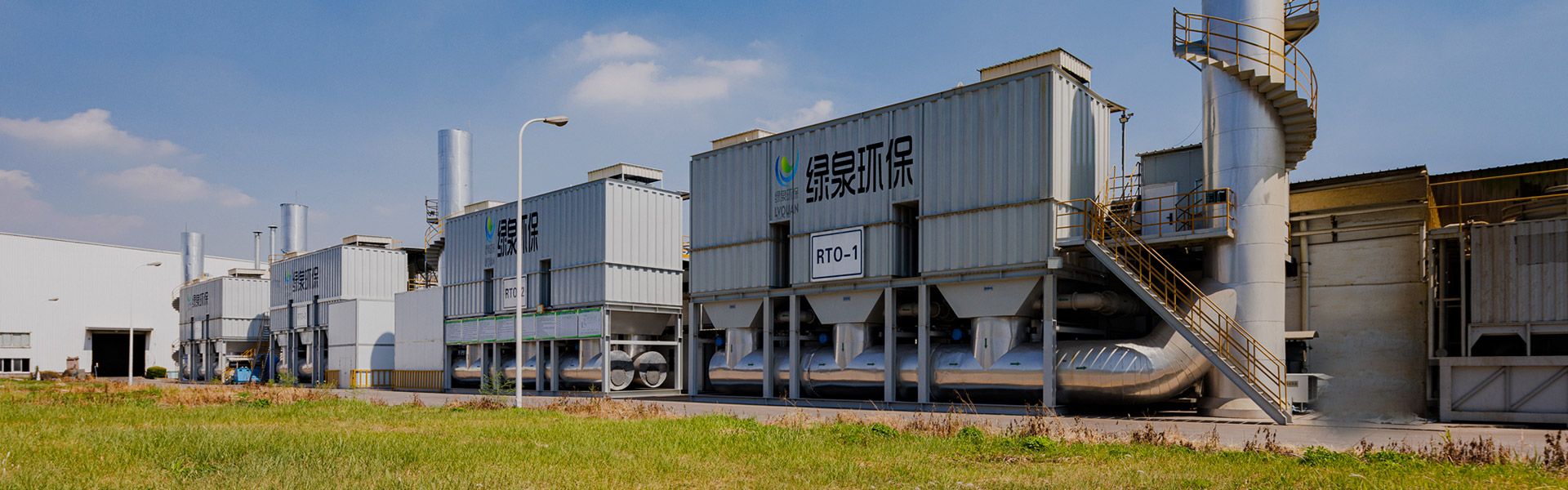
Content
LQ-RCO heat-storage catalytic incineration equipment is industrial VOC treatment equipment built to break down organic compounds in factory exhaust streams into carbon dioxide and water vapor through a regenerative catalytic oxidizer process. In plain terms, the system pulls in solvent-laden or odor-bearing waste gas, raises its temperature with the help of stored heat rather than fresh fuel for most of the cycle, passes the stream through a catalyst bed at a moderate reaction temperature, and releases a treated gas stream that carries far fewer volatile organic compounds than the inlet stream. This type of heat storage incinerator is commonly installed downstream of painting lines, ovens, printing presses, and chemical reactors where continuous waste gas treatment is required.
As a piece of incineration equipment, the LQ-RCO regenerative catalytic oxidizer combines low-temperature catalytic oxidation with ceramic heat storage technology. This pairing is what allows the unit to recover a large share of the reaction heat and reuse it to preheat incoming waste gas, which in turn reduces auxiliary fuel or electric heating demand and lowers the temperature of the gas leaving the stack. The equipment shown below is a representative LQ-RCO heat-storage catalytic incineration equipment installation, with the housing, inspection panels, and connecting ductwork visible on the exterior.
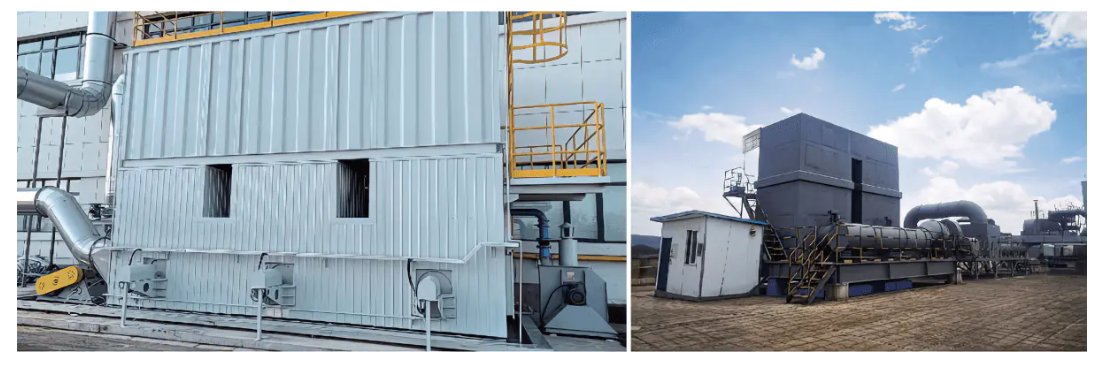
Figure 1. LQ-RCO heat-storage catalytic incineration equipment on site, shown with the insulated housing on the left and an installed unit with connecting ductwork on the right.
Understanding the thermal oxidizer working principle of an RCO system starts with the startup sequence. Before waste gas is connected to the equipment, the heating chamber and the ceramic heat storage bed are preheated electrically. Once the set temperature is reached, the waste gas source is opened and a matching fan draws the gas into the unit. The incoming stream first exchanges heat with a preheated heat storage ceramic body, picking up a first temperature rise, then enters a heating zone for a second temperature increase until it reaches the level needed for the catalytic reaction.
From there, the gas enters the catalytic chamber, where the organic compounds react over the catalyst bed to form carbon dioxide and water while releasing heat energy. The treated, clean gas then gives part of that heat back to a second heat storage ceramic body before it is discharged by the fan. An inlet thermocouple on the exhaust fan side continuously checks the gas temperature, and once the set point is reached the switching valve changes position so the waste gas stream and the clean gas stream swap chambers. This regenerative cycle repeats continuously, which is the core idea behind every regenerative catalytic oxidizer and is also the reason the technology is sometimes grouped together with a regenerative thermal oxidizer in general thermal oxidizer diagram references, even though the two use different reaction temperatures.
Figure 2. Simplified isometric view of an RCO system housing, with the catalytic chamber, twin heat storage chambers, inlet and switching valves, thermocouple, and fan positions labeled for reference.
Most catalytic incinerator designs of this type run on two heat storage chambers that take turns absorbing and releasing heat, and the LQ-RCO can also be configured with three chambers when a higher purification efficiency target is required. In what can be called Process 1, the first chamber absorbs heat from the incoming exhaust gas while the second chamber is releasing stored heat as clean gas passes through it on its way out. After the switching valve changes position, the roles reverse in Process 2, the first chamber now releases the heat it stored while the second chamber begins absorbing heat from the next batch of incoming exhaust gas. The catalytic chamber sits between the two heat storage chambers and is where the actual catalytic decomposition of organic compounds takes place in both processes.
| Stage | Process 1 | Process 2 |
|---|---|---|
| First chamber | Absorbs heat from incoming exhaust gas | Releases stored heat as clean gas is discharged |
| Second chamber | Releases stored heat as clean gas is discharged | Absorbs heat from incoming exhaust gas |
| Catalytic chamber | Catalytic decomposition of organic compounds | Catalytic decomposition of organic compounds |
Because the catalyst lowers the temperature needed for oxidation, the LQ-RCO catalytic combustion system typically reacts at 250°C to 500°C, well below the temperature an open flame thermal oxidizer needs to reach the same destruction outcome. Operating in this lower temperature window is also why the equipment is described as a low temperature oxidation system, and it is one reason nitrogen oxide formation stays low compared with high-temperature combustion methods. According to the manufacturer specification sheet, a two-chamber RCO configuration generally reaches a purification efficiency of around 95 percent, while a three-chamber configuration can reach over 98 percent, and the equipment series as a whole is rated at 99 percent or higher purification efficiency under standard test conditions. Thermal recovery efficiency, which reflects how much of the reaction heat is reused to preheat incoming gas rather than lost up the thermal oxidizer stack, generally reaches over 95 percent, and energy consumption can be as low as 8 watt-hours per normal cubic meter of treated gas.
The chart above compares typical purification efficiency between a two-chamber and a three-chamber RCO arrangement. Adding a third heat storage chamber gives the gas stream an additional pass through the regenerative bed, which is why the three-chamber layout tends to post a higher efficiency figure on the same waste gas treatment duty. This difference matters most when a facility faces a strict organic waste gas discharge limit or when the inlet concentration of solvent vapor is relatively high. For lighter duty applications, a two-chamber RCO system can still comfortably meet most regional waste gas treatment requirements while keeping the equipment footprint and ceramic heat storage volume smaller. Choosing between the two configurations is generally a balance between the required purification efficiency, the available installation space, and the characteristics of the specific waste gas stream being treated.
In everyday plant language, the terms thermal oxidizer and incinerator are often used loosely for the same family of equipment that uses heat to destroy organic vapors. The practical difference usually comes down to temperature and catalyst use. A general incinerator or a regenerative thermal oxidizer typically relies on heat alone and needs higher chamber temperatures, often in the range of 700°C to 800°C or more, to destroy the same organic load that an RCO catalytic incinerator can treat at 300°C to 500°C. An acid gas incinerator is a related category built with corrosion resistant materials for streams that form acidic byproducts during combustion, and it usually still depends on pure thermal destruction rather than a catalyst bed.
A flare is generally used for intermittent, high volume, or safety-relief gas streams rather than continuous low concentration solvent vapor, and it rarely includes heat recovery. A regenerative thermal oxidizer or RCO system, by contrast, is built for continuous duty waste gas treatment and is paired with heat storage so that most of the reaction energy is reused rather than released directly to atmosphere. This is part of why catalytic oxidizer equipment is more commonly selected for steady-state painting lines, PCB manufacturing exhaust, and similar continuous organic waste gas treatment duties, while flares remain more common for occasional or emergency gas relief.
The radar chart above gives a general, qualitative picture of how catalytic oxidation compares with thermal-only oxidation and with flaring across five characteristics commonly discussed in industry literature: required operating temperature, energy efficiency, NOx formation control, equipment footprint, and degree of heat recovery. These ratings describe broad technology patterns rather than guaranteed outcomes for any specific site, since actual results depend on the waste gas composition, flow rate, and concentration at a given facility. Catalytic oxidation generally needs a lower reaction temperature and tends to show stronger heat recovery and NOx control relative to flaring, which mainly trades footprint and continuous operation for simplicity in handling intermittent gas. A regenerative thermal oxidizer sits between the two on most of these dimensions, since it recovers heat similarly to an RCO system but without lowering the reaction temperature through a catalyst. Engineers typically use comparisons like this as a starting point and then confirm the right technology with a waste gas composition analysis specific to the process line being treated.
The LQ-RCO VOC equipment line is organized into twelve standard models, running from RCO-10 up to RCO-200, so that a facility can match the treatment air volume to the actual exhaust flow coming off its production line rather than oversizing or undersizing the unit. Treatment air volume scales from 1000 cubic meters per hour on the smallest RCO-10 model up to 20000 cubic meters per hour on the RCO-200 model, and heating power scales from 30 kilowatts up to 300 kilowatts across the same range. Other air volume specifications outside this standard table can also be designed on request, and fuel preheating can be added when it is specified at the time of ordering.
This line chart tracks treatment air volume across all twelve standard RCO models, and the steady upward curve shows how closely the model series follows actual exhaust flow requirements rather than jumping in large, hard to match steps. A facility with a single small painting booth might be well served by an RCO-10 or RCO-15 rated for 1000 to 1500 cubic meters per hour, while a larger multi-line coating operation may need an RCO-60 or above. Because the curve is fairly smooth between adjacent models, most exhaust flow rates measured during a site survey can be matched to a standard model without resorting to a fully custom design. This kind of model-to-flow mapping is a common first step in specifying an RCO system, since treatment air volume largely determines vessel size, fan selection, and ductwork diameter. Matching air volume correctly also has a direct effect on energy consumption, since an oversized unit processing a smaller actual flow tends to use more energy per unit of waste gas treated than a properly sized one.
The column chart above shows installed heating power for the same twelve RCO models, which rises from 30 kilowatts on the RCO-10 to 300 kilowatts on the RCO-200. Heating power mainly covers the electric heating tubes used during startup and during periods when the waste gas heating value is not enough on its own to sustain the catalytic reaction temperature. Because the heat storage ceramic bed recovers a large share of the reaction heat once the unit reaches steady operation, the installed heating power is generally needed only intermittently rather than continuously. Larger models need proportionally more heating power mainly because they hold a larger volume of heat storage ceramic and catalyst, which takes more energy to bring up to temperature during a cold start. Reviewing this heating power curve alongside the treatment air volume curve gives a reasonably complete first picture of both the thermal and the flow capacity needed before moving into a detailed equipment selection.
| Parameter | RCO-10 | RCO-15 | RCO-20 | RCO-30 | RCO-40 | RCO-50 | RCO-60 | RCO-80 | RCO-100 | RCO-150 | RCO-180 | RCO-200 |
|---|---|---|---|---|---|---|---|---|---|---|---|---|
| Treatment air volume (m3/h) | 1000 | 1500 | 2000 | 3000 | 4000 | 5000 | 6000 | 8000 | 10000 | 15000 | 18000 | 20000 |
| Catalytic temperature | 300-500°C | 300-500°C | 300-500°C | 300-500°C | 300-500°C | 300-500°C | 300-500°C | 300-500°C | 300-500°C | 300-500°C | 300-500°C | 300-500°C |
| Purification efficiency | 99%+ | 99%+ | 99%+ | 99%+ | 99%+ | 99%+ | 99%+ | 99%+ | 99%+ | 99%+ | 99%+ | 99%+ |
| Heat accumulator (L) | 288 | 512 | 548 | 970 | 1160 | 1570 | 1800 | 2600 | 3200 | 4610 | 5410 | 6280 |
| Catalyst amount (L) | 72 | 128 | 162 | 242 | 288 | 392 | 450 | 648 | 800 | 1160 | 1360 | 1570 |
| Heating power (kW) | 30 | 36 | 42 | 54 | 65 | 75 | 90 | 120 | 150 | 200 | 250 | 300 |
| Length L (mm) | 1350 | 1650 | 1800 | 2100 | 2300 | 2600 | 2700 | 3200 | 3500 | 4100 | 4400 | 4700 |
| Width B (mm) | 1350 | 1650 | 1800 | 2100 | 2300 | 2600 | 2700 | 3200 | 3500 | 4100 | 4400 | 4700 |
| Height H (mm) | 2600 | 2700 | 2800 | 3100 | 3200 | 3300 | 3500 | 4000 | 4500 | 5000 | 6000 | 6500 |
| Air duct diameter (mm) | 200 | 220 | 250 | 300 | 350 | 400 | 450 | 500 | 600 | 700 | 750 | 800 |
Two notes apply across the whole table. First, air volume specifications outside this standard range can still be designed on a project basis when a facility's exhaust flow falls between two standard models or exceeds the RCO-200 rating. Second, the explosion-proof form used across the LQ-RCO line is a membrane type relief design, which applies regardless of which model is selected.
Solvent waste gas treatment needs show up across a wide range of manufacturing sectors, and the LQ-RCO equipment line is generally specified wherever a process line releases organic vapor that needs to be captured and treated before discharge. Common applications include the following.
Across these sectors, the common thread is a continuous or semi-continuous exhaust stream containing benzene, ketone, ester, alcohol, ether, aldehyde, phenol, or similar organic compounds along with general odor. This is the type of waste gas profile that an RCO catalytic oxidizer is generally suited to treat, since the catalyst bed is selected to work across this broad family of organic compounds rather than a single specific solvent.
When a facility is comparing air pollution control equipment options for a new or upgraded exhaust gas treatment system, a regenerative catalytic oxidizer tends to come up for a consistent set of reasons. The combination of low-temperature oxidation and ceramic heat storage means less auxiliary energy is needed to sustain the reaction once the unit is up to temperature, which is reflected in the low energy consumption figures discussed earlier. Operating at 250°C to 500°C instead of the higher range used by pure thermal oxidation also limits NOx formation, supporting the equipment's no secondary pollution rating under normal operating conditions.
Taken together, these characteristics are why a VOC incineration system built around regenerative catalytic oxidation is frequently selected for continuous duty exhaust gas treatment system needs in coating, electronics, printing, and chemical processing settings, where both the regulatory discharge limit and the day-to-day operating cost of the equipment matter to the facility.
Lvquan Environmental Protection Engineering Technology Co., Ltd. is based in Gaoyou, Yangzhou, a city often referred to as the north gate of Jiangsu province. The company is a joint-stock enterprise formed through cooperation between professionals who each carry more than 30 years of experience in VOCs equipment design and manufacturing, and it operates as a dedicated VOCs organic waste gas treatment engineering equipment manufacturer.
The company holds a registered capital of 22 million yuan, with fixed assets of close to 40 million yuan and total assets of close to 60 million yuan. Manufacturing takes place across a factory floor area of about 9800 square meters, supported by more than 200 sets of various machining equipment and a team of about 120 employees, with an annual production capacity figure of around 100 million yuan. This scale of in-house manufacturing supports the fabrication of heat-storage catalytic incineration equipment, including the LQ-RCO series described in this article, from structural housing through to final assembly and testing.
Q1. What is regenerative catalytic oxidation used for?
Regenerative catalytic oxidation is used to treat organic waste gas from industrial exhaust streams, converting volatile organic compounds into carbon dioxide and water through a catalyst bed combined with ceramic heat storage, which reduces the energy needed to sustain the reaction.
Q2. What is the difference between an RCO system and a regenerative thermal oxidizer?
An RCO system uses a catalyst to lower the required reaction temperature, typically to around 300°C to 500°C, while a regenerative thermal oxidizer generally relies on heat alone and needs a higher chamber temperature to reach a comparable destruction outcome.
Q3. What catalytic temperature does the LQ-RCO equipment operate at?
The LQ-RCO catalytic chamber generally operates between 300°C and 500°C, which is the temperature range needed for the catalytic decomposition reaction that produces carbon dioxide and water from the organic compounds in the waste gas.
Q4. How does the switching valve affect waste gas treatment?
The switching valve changes the flow path once the exhaust fan inlet thermocouple confirms the set temperature has been reached, sending waste gas into the chamber that was previously releasing heat to clean gas, which keeps the regenerative cycle running continuously.
Q5. Can the LQ-RCO equipment be customized for a specific air volume?
Yes, the standard model range covers 1000 to 20000 cubic meters per hour across twelve models, and air volume specifications outside this range can be designed separately based on a facility's actual exhaust flow.
")
Overview Of Variable Freouency Zeolite Turntable Our company's zeolite concentration turntable uses a combination of zeolite modules, with a high zeol...
See Details
Overview of Activated Carbon Fiber Organic Solvent Purification Recovery Device The Activated Carbon Fiber Organic Solvent Purification Recovery Syste...
See Details
Overview The VOC-ACA series organic gas particle carbon purification and recovery equipment is used for the absorption, recovery, and reuse of organic...
See Details
Product Introduction Gas heat exchanger is mainly used for energy saving and emission reduction industries in the waste heat recovery of flue gas in v...
See Details+Regenerative Thermal Oxidizer (RTO)")
The Concept Of The Complete Set Of Equipment The purpose of employing rotary drum zeolite adsorption for organic waste gas is to concentrate low-conce...
See Details")
Concept Of Fixed Bed Zeolite + Catalytic Combustion As A Set Of Equipment The fixed bed zeolite + catalytic combustion device is suitable for the conc...
See Details+ Catalytic Oxidation (CO)")
Concept Of Zeolite Rotary Wheel + Catalytic Combustion As A Set Of Equipment In the combined process of organic waste gas and waste gas treatment, the...
See Details+Thermal Oxidizer (TO)")
The Concept Of Zeolite Wheel+ Direct Combustion High-Temperature Incineration Equipment The purpose of employing rotary drum zeolite adsorption for or...
See Details
Purpose Mainly used for proportional ventilation of high-temperature flue gas. lt is widely used in places where leak rate requirements are not high, ...
See Details
Overview The wet dust removal principle uses the process of capturing and separating dust particles in the gas phase by fully contacting gas-liquid tw...
See DetailsMOBILE
Product Manual

Copyright © Lv quan Environmental Protection Engineering Technology Co., Ltd. All Rights Reserved. Vocs Organic Waste Gas Treatment Engineering Equipment Manufacturer

