

 English
 русский
 Français
 Español
 عربى
عربى
LQ-RTO Heat-storage high-temperature incineration equipment
Cat:Equipment
Overview Of Tower-Type RTO Regenerative Thermal Oxidizer (RTO) is an organic waste gas treatment equipment that combines high-temperature oxidation wi...
See Details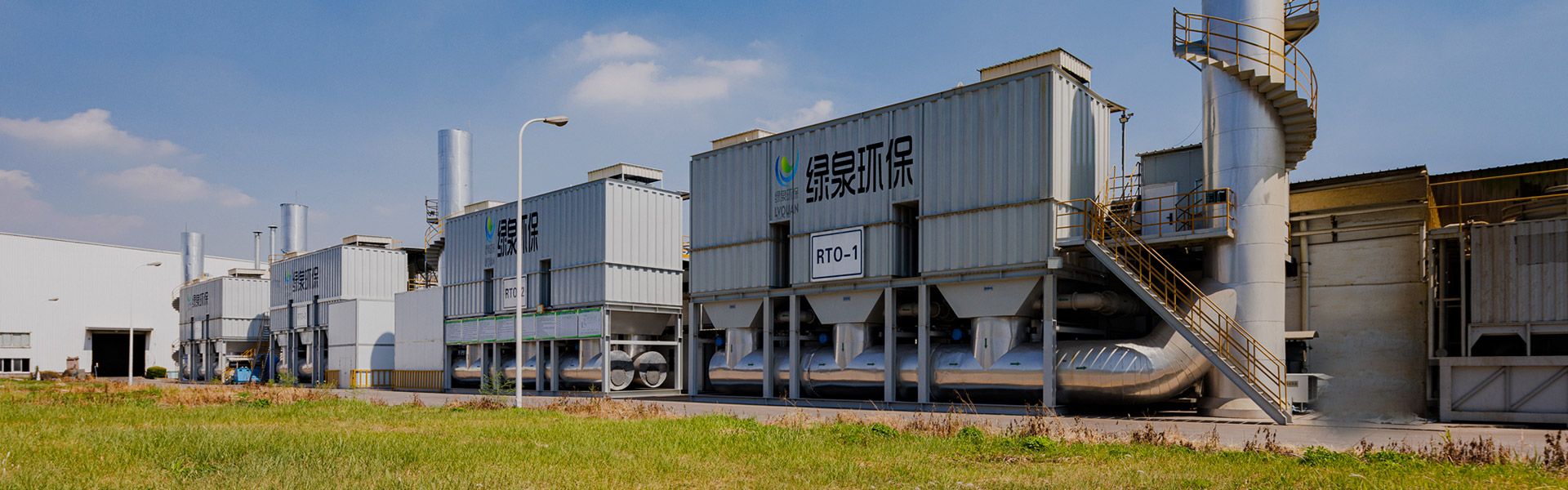
Content
A pickling tank lid opens for thirty seconds during loading, and a white plume drifts across the roof steel. Six months later the beams are stained, the cable trays smell of acid, and the repair estimate is larger than the price of the abatement equipment that should have prevented the problem. The conclusion comes first: the difficulty is rarely the fan or the stack height. It is that the HCl scrubber was chosen on tower diameter and purchase price instead of on the three numbers that actually govern absorption, which are inlet mist loading, gas temperature and the required outlet concentration.
An HCl scrubber, also described as a hydrochloric acid scrubber, a hydrogen chloride scrubber or an acid fume scrubber, is a wet scrubbing device that brings a gas stream containing hydrogen chloride into contact with a liquid, usually water or water dosed with a small amount of caustic soda, so that the HCl transfers from the gas phase into the liquid. The chemistry is genuinely easy, because HCl is extremely soluble in water at roughly 700 grams per kilogram of water at room temperature. The difficulty sits in contacting, cooling, droplet removal and corrosion control, and that is where most projects either succeed or quietly fail.
This article covers what an HCl scrubber must remove, where hydrogen chloride appears in real plants, how a packed bed works internally, the design values and tolerances that decide performance, reagent and material selection, where the scrubber belongs in a process train that also contains VOC abatement equipment, maintenance routines, common failure modes, procurement questions and cost drivers.
Key point: HCl removal is easy chemistry wrapped in hard mechanical engineering. Cool the gas, keep the packing wet, hold the pH in band and strip the droplets out, and the rest is detail.
Designers who treat an HCl scrubber as a gas absorption device alone tend to undersize the downstream stages. In practice the inlet stream arriving at the scrubber usually contains hydrogen chloride in two forms at the same time. Part of it is true gas, molecular HCl that will absorb into a wetted surface within a very short contact time. The other part is acid mist, a suspension of fine droplets formed when hot acid vapour meets cooler moist air, when a tank surface splashes, or when a gas stream cools through its dew point inside a duct.
The split between gas and mist matters because the two behave differently. Molecular HCl is controlled by liquid to gas ratio, packing surface area and pH. Mist is a particle problem. Droplets above roughly ten microns are captured reasonably well by a chevron mist eliminator, but droplets in the sub-micron range follow the gas stream through the packing bed almost untouched and can account for most of the chloride that a stack test measures. This is why two plants with identical inlet concentrations can report very different outlet figures: their droplet size distributions are not the same.
Three physical facts shape the whole design. First, the solubility of HCl in water falls as the liquid warms and as its acid concentration rises, so a scrubber recirculating hot, saturated liquor will release HCl back into the gas. Second, the absorption of HCl into water is strongly exothermic, releasing roughly 75 kilojoules per mole, so liquor temperature climbs unless the sump is cooled or bled. Third, aqueous hydrochloric acid reaches a constant boiling point near 20.2 percent HCl at about 108.6 degrees Celsius, which is the reason hot concentrated acid baths produce a vapour that does not simply condense out in a cold duct.
Key point: A chlorides problem on the stack is often a droplet problem, not an absorption problem, so the mist eliminator and its wash system deserve the same engineering attention as the packing bed.
Hydrogen chloride is generated or released in far more places than the classic steel pickling line, and the source determines the scrubber configuration. The following list covers the situations that most often justify a dedicated HCl scrubber in industrial settings.
Because the same equipment family serves all of these cases, a buyer comparing quotations should expect very different designs at similar gas flows. A tank vent with 40 degrees Celsius gas and 200 milligrams per cubic metre of HCl is a different machine from an incinerator flue gas at 180 degrees Celsius carrying ash and 3,000 milligrams per cubic metre of HCl.
Key point: Always state the source process, the gas temperature, the moisture content and the expected chloride form when requesting a quotation, because those four facts change the scrubber far more than the gas flow does.
A vertical counter-current packed scrubber remains the workhorse for HCl service because it delivers a large wetted surface area in a small footprint at modest pressure drop. Gas enters at the bottom, passes up through a support plate and a bed of random or structured packing, meets liquid falling from a distributor above, and exits through a mist eliminator. Liquid collects in the sump, is recirculated by a pump, and is partly purged to control dissolved salt and suspended solids.
Each internal component has a job, and each one has a characteristic way of going wrong. The table below summarises the typical arrangement and the field mistakes that most often reduce performance after commissioning.
| Component | Function | Common field mistake |
|---|---|---|
| Inlet quench or spray chamber | Cools the gas, knocks out coarse droplets and captures part of the dust load | No cooling margin, so gas arrives above the temperature limit of the packing and the shell |
| Packing bed | Provides wetted surface area for absorption of HCl gas | Bed depth chosen by rule of thumb rather than by transfer units |
| Liquid distributor | Spreads irrigation evenly across the full cross section | Too few nozzles, or orifices that plug within months on hard water |
| Mist eliminator | Removes entrained droplets that carry most of the residual chloride | Face velocity too high, or no wash header to keep the vanes clean |
| Recirculation pump and sump | Holds the liquid to gas ratio steady and provides buffer volume | Pump selected for clean water with no allowance for solids or salt |
| Caustic dosing and pH control | Keeps the scrubbing liquor in the alkaline band that suppresses HCl slip | A single probe in a dead zone of the sump, with manual dosing |
| Exhaust fan | Moves gas through packing, eliminator, duct and stack | Wheel material not rated for wet chloride, leading to rapid corrosion |
| Blowdown and purge | Controls dissolved salt, suspended solids and chloride build-up | No purge, so salts climb until efficiency and pump life both fall |
A useful way to think about the tower is as a counter-current heat and mass exchanger. Every kilogram of HCl absorbed carries heat into the liquor, and every litre of recirculated liquid carries some heat back to the gas. If the sump is not cooled, bled or replenished, the equilibrium shifts against absorption and the same tower that passed a performance test in winter can drift out of compliance in summer.
Key point: Specify the mist eliminator, the distributor and the purge system as engineering items, not as accessories, because those three items explain most of the gap between design efficiency and measured stack results.
Design values for HCl scrubbers are not secrets, but they are frequently omitted from quotations. Asking a supplier to confirm each figure below in writing turns a vague technical discussion into a verifiable design. The ranges shown are the values that most industrial projects settle into after balancing efficiency, pressure drop and reagent consumption.
| Parameter | Typical range | Why it matters |
|---|---|---|
| Superficial gas velocity in the packed bed | 1.0 to 1.8 metres per second, below about 70 percent of flooding | Higher velocity raises pressure drop and entrainment sharply |
| Liquid to gas ratio | 1.5 to 3 litres per cubic metre for HCl, higher when dust is present | Too low and parts of the packing run dry, creating acid slip |
| Sump liquor temperature | Keep below 50 to 60 degrees Celsius | Warm liquor raises HCl vapour pressure and reduces net absorption |
| pH setpoint in the sump | 8 to 9, measured in a flowing line | Below 7.5 gives acid slip; above 10 wastes reagent and absorbs carbon dioxide |
| Packing height per stage | 1.5 to 3 metres, set by required transfer units | Arbitrary height wastes fan energy or sacrifices efficiency |
| Pressure drop per stage | 400 to 1,000 pascals | Must be budgeted in fan selection, not discovered after installation |
| Outlet droplet carry-over | Essentially free of droplets above about 10 microns | Droplets can dominate the measured stack concentration of chloride |
| Number of stages | One for light loads, two for heavy loads or tight limits | Two moderate stages usually outperform one very tall stage |
Staging deserves a separate comment. Efficiency is not linear in packing height, because the driving force shrinks as the gas becomes cleaner. A single stage with three metres of packing may deliver 97 percent removal, while two stages with 1.5 metres each, using separate liquid loops, can deliver above 99 percent for a similar total height. The second stage works with cleaner liquor at a higher pH, which restores the driving force that the first stage has already consumed.
Temperature is the parameter that buyers underestimate most often. An inlet at 120 degrees Celsius will evaporate a large share of the recirculated liquid, concentrate the sump and raise the vapour pressure of HCl over the liquor. Either the gas is cooled before it reaches the packing, or the tower is designed as a combined quench and absorption unit with a larger sump, more make-up water and a higher blowdown rate.
Key point: Liquid to gas ratio, pH and liquor temperature control efficiency far more than tower height does, so these three values should appear as guarantees in any technical agreement.
Configuration choices explain most of the cost difference between quotations for the same duty. The chart below summarises the removal efficiency that typical configurations achieve in industrial service, drawn on a 50 to 100 percent scale so that the high-efficiency options remain distinguishable from one another.
Indicative HCl removal efficiency by scrubbing configuration
Bars are drawn on a 50 to 100 percent scale for readability. The numeric range for each configuration is shown beside the label. Values are indicative and depend on inlet load, gas temperature, droplet size distribution and maintenance quality.
The trend that matters is the flattening at the right-hand side. Moving from a spray-only chamber to a single packed stage with pH control is a large step that usually costs little more than good instrumentation and a dosing system. Moving from one packed stage to two, or adding a high-energy venturi and a fibre-bed eliminator, adds substantial capital and operating cost for a comparatively small additional gain. Those extra steps are justified only when the emission limit is tight in absolute terms, when the inlet load is high, or when the gas carries fine mist and dust that a packed bed cannot manage.
The second observation concerns pressure drop, which is the hidden operating cost in every configuration. A two-stage packed tower with a high-efficiency eliminator may draw two to three times the fan power of a single-stage unit, and that energy bill continues for the entire life of the plant. Buyers who compare only equipment price often discover the difference in the electricity account rather than in the purchase order.
A third point is that high nominal efficiency is only meaningful when it can be maintained. A configuration that reaches 99 percent when the packing is clean and the nozzles are clear may settle at 93 percent after six months of scaling, salt deposition and blocked spray orifices. Robust, maintainable designs frequently outperform elegant ones that demand attention the plant cannot provide.
Key point: Choose the simplest configuration that meets the limit with margin, then spend the remaining budget on instrumentation, materials and accessibility rather than on an extra stage or a high-energy venturi.
Because HCl is so soluble, water alone will absorb a large fraction of it. Water-only scrubbing works while the liquor stays dilute and cool, but the sump acidifies quickly under continuous load, and once the pH falls below about 2 the liquor begins to release HCl back to the gas. That is why most industrial HCl scrubbers use a small caustic dose to hold the liquid in the alkaline band, which keeps the equilibrium strongly in favour of absorption and reduces the sensitivity of performance to small changes in load.
The stoichiometry is simple and worth knowing before a reagent contract is signed. Neutralising one kilogram of HCl requires about 1.1 kilograms of pure sodium hydroxide, which corresponds to roughly 3.4 kilograms of a 32 percent caustic solution. A tank vent emitting 1,000 cubic metres per hour at 500 milligrams per cubic metre of HCl therefore carries about 0.5 kilograms of HCl per hour and consumes roughly 0.55 kilograms of pure NaOH per hour, or about 1.7 kilograms of 32 percent solution per hour, before any allowance for purge losses, carbon dioxide absorption and dosing overshoot.
| Reagent | Typical strength | Where it fits | Drawbacks |
|---|---|---|---|
| Water only | Fresh make-up, pH allowed to fall | Very light loads, batch tank vents, temporary operation | Liquor acidifies, efficiency collapses as pH falls, high corrosion of the sump |
| Sodium hydroxide solution | 20 to 32 percent commercial solution, dosed to pH 8 to 9 | Most industrial HCl scrubbers, from tank vents to incinerator flue gas | Higher reagent cost per kilogram than lime, slippery when spilled, needs dosing control |
| Sodium carbonate solution | 10 to 20 percent | Small systems where a milder alkali is preferred | Lower neutralising capacity per kilogram, foaming in some designs |
| Hydrated lime slurry | 5 to 15 percent suspended solids | Large gas volumes where reagent cost dominates | Scaling on packing and nozzles, sludge handling, abrasive to pumps |
| Magnesium hydroxide slurry | 5 to 15 percent | Systems where a soluble salt and lower scaling are preferred | Slower reaction, higher recirculation rate, higher pump wear |
| Sodium hypochlorite or hydrogen peroxide | Dilute, dosed separately | Odour and reduced sulphur compounds, not HCl removal itself | Adds cost and complexity if the gas does not need oxidation |
Control philosophy matters as much as reagent choice. A pH probe mounted in a stagnant sump corner will read a value that has little to do with what the packing actually sees. The probe belongs in the recirculation line, in flowing liquor, with a second probe for cross-checking and a two-point calibration routine that is documented. Proportional dosing with a small dead band, rather than on-off control, avoids the pH swings that alternately starve the packing of alkali and dump excess reagent into the purge.
Key point: Reagent cost is only a small part of life-cycle cost, but poor pH control is expensive in every direction, because it damages the shell, wastes caustic and lets chloride slip past the packing.
Hydrochloric acid is aggressive to most common metals in the presence of moisture, and the scrubber is by definition a wet environment. Material selection therefore drives both service life and the maintenance budget, and the temperature at each point in the system sets the limit on what can be used. The highest-risk locations are usually the inlet duct where hot acid vapour first meets cooler metal, the pump casing and impeller, the mist eliminator support, the fan wheel and any stainless steel fasteners.
| Material | Practical temperature limit | Notes for HCl service |
|---|---|---|
| PVC | About 55 to 60 degrees Celsius | Low cost, good chemical resistance, but softens quickly if the quench fails |
| Polypropylene | About 90 to 100 degrees Celsius | Widely used for shells, packing and ducts; poor resistance to strong oxidisers |
| CPVC | About 90 to 95 degrees Celsius | Better temperature margin than PVC, useful for small pipework and headers |
| FRP with vinyl ester resin | About 95 to 120 degrees Celsius | Excellent for large shells; resin grade, cure and liner quality decide the life |
| PVDF | About 140 degrees Celsius | Used for nozzles, linings and high-value internals; expensive but durable |
| PTFE and PFA | Above 200 degrees Celsius | Common for gaskets, seals and hot duct liners |
| Rubber-lined carbon steel | About 70 to 90 degrees Celsius, lining dependent | Structurally strong; pinholes in the lining are the main failure mode |
| Titanium and high-nickel alloys | Application dependent | Resistant in many wet chloride services, but selection must be confirmed case by case |
Gaskets, fasteners and small parts cause a disproportionate share of failures. An EPDM or PTFE-enveloped gasket on a flanged duct may outlive the entire structure, while a plain carbon steel bolt in the same flange will be gone within a year. Designers should specify the whole fastener assembly in a chloride-resistant grade, or isolate flanges so that bolts never contact the wet gas path.
Dry and wet conditions also demand different choices. Anhydrous hydrogen chloride is a very different corrosion problem from hydrochloric acid solution, and some alloys that thrive in wet chloride are attacked in dry gas and vice versa. Any material selection should be confirmed against the specific concentration, temperature, oxygen content and flow condition at each location rather than against a general acid-resistance table.
Key point: Spend the material budget on the wet-dry boundary, the fan and the small parts, because those three areas decide whether the scrubber reaches its fifteenth year in service.
Placement is a design decision with long-term consequences for every downstream item. The three common positions are upstream of a thermal oxidiser, downstream of an incinerator or oxidiser, and as a stand-alone unit on tank vents or a combined acid exhaust header. Each position imposes different requirements on materials, temperature handling and instrumentation.
For a tank vent or a combined acid exhaust header, the scrubber usually sits at the end of the line with a fan pulling gas through it. In this arrangement the gas is often near ambient and the main design drivers are mist loading, moisture and the presence of other acid species. A pre-scrub stage is still worthwhile when the exhaust contains a mixture of fine acid mist and coarse droplets from splashing, because the first wet stage absorbs the impact of the droplets and protects the packing above it.
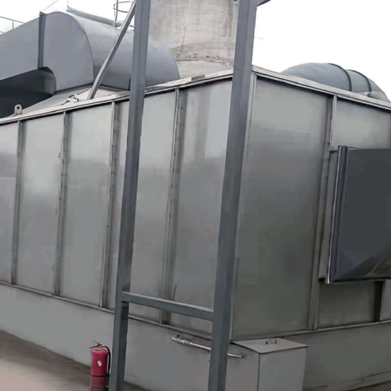
For that first wet stage and for many small and medium tank vent duties, a horizontal spray cabinet provides a compact contact chamber with generous liquid to gas contact, low pressure drop and good tolerance for dust and splash carry-over. It is often the natural place to absorb the initial chloride load, reduce the gas temperature and remove the coarse droplet fraction before a packed bed finishes the job. A representative example of this equipment family is shown below.
When the scrubber is placed upstream of a thermal oxidiser, its role changes from final abatement to protection. Chloride entering a regenerative thermal oxidiser or a catalytic system can attack refractory, corrode heat exchange surfaces and deactivate catalyst, and it also forms secondary pollutants that must be handled later. Removing the bulk of the HCl before the oxidiser, then polishing the small residual after it, is a configuration that appears repeatedly in plants handling chlorinated waste streams.
Key point: Decide placement on the basis of what the chloride does to the equipment downstream, not only on where the gas is coolest, because protecting an oxidiser is usually cheaper than repairing one.
Almost every HCl scrubber that underperforms shares one root cause: the gas arrived hotter than the packing could tolerate. Incinerator flue gas, oxidiser exhaust and hot tank vents can reach temperatures well above the softening point of common plastics, and in those cases the cooling duty must be handled deliberately rather than by spraying water and hoping for the best.
Two approaches dominate. The first is evaporative quenching, in which a fine water spray cools the gas adiabatically and saturates it with moisture. Quenching is cheap in capital terms but consumes water permanently and increases the moisture load on the downstream packing and fan. The second is recuperative cooling, in which the hot gas gives up heat to a cooler stream through a gas heat exchanger. This approach reduces water consumption, allows heat to be recovered for process use, and gives much tighter control of the temperature entering the packed bed.
A gas heat exchanger placed between a hot source and the scrubber is particularly useful when the gas stream is large, when water supply is limited or when the plant is looking to recover energy. It also protects the duct and the fan from thermal excursions that would otherwise shorten equipment life. The example below belongs to this equipment family.
Temperature control targets worth writing into a specification include an inlet temperature to the packed bed that stays comfortably below the temperature limit of the shell and packing material, a sump temperature that stays below about 50 to 60 degrees Celsius, and a quench control loop that responds to gas temperature rather than to a fixed water flow. Instruments should include a temperature element at the tower inlet and in the sump, plus a low-flow alarm on the quench water line, because the failure of a quench pump is one of the fastest ways to destroy a plastic tower.
A final point concerns ductwork. Uninsulated duct between the process and the scrubber frequently runs below the acid dew point, which allows condensation to form on the walls. The condensate is hydrochloric acid, and it will find every low point, flange and support bracket. Insulation, drainage at low points and a slight slope toward a drain are small costs that prevent large repairs.
Key point: Define the cooling duty as an engineered function with instrumentation and alarms, because a failed quench or heat exchanger will take the tower, the fan and the duct with it.
Many plants discover the HCl problem only after installing VOC abatement equipment. Streams containing chlorinated solvents, such as methylene chloride used in pharmaceutical extraction or perchloroethylene used in some cleaning operations, pass through a thermal oxidiser and emerge as a mixture of carbon dioxide, water, hydrogen chloride and occasionally chlorine. That mixture cannot be vented directly, and it cannot be sent to a scrubber designed only for low-concentration tank vents either.
The typical arrangement is a three-step train. First, the oxidation step destroys the organic compounds at a temperature and residence time that achieve the required destruction efficiency. Second, a quench or heat exchanger reduces the gas temperature quickly, which limits the formation of unwanted by-products and protects the downstream materials. Third, an alkaline scrubber removes the HCl that was created in the first step. Where the chloride load entering the oxidiser is already high, a pre-scrubber removes the bulk of it before oxidation, and the post-scrubber polishes the residual.
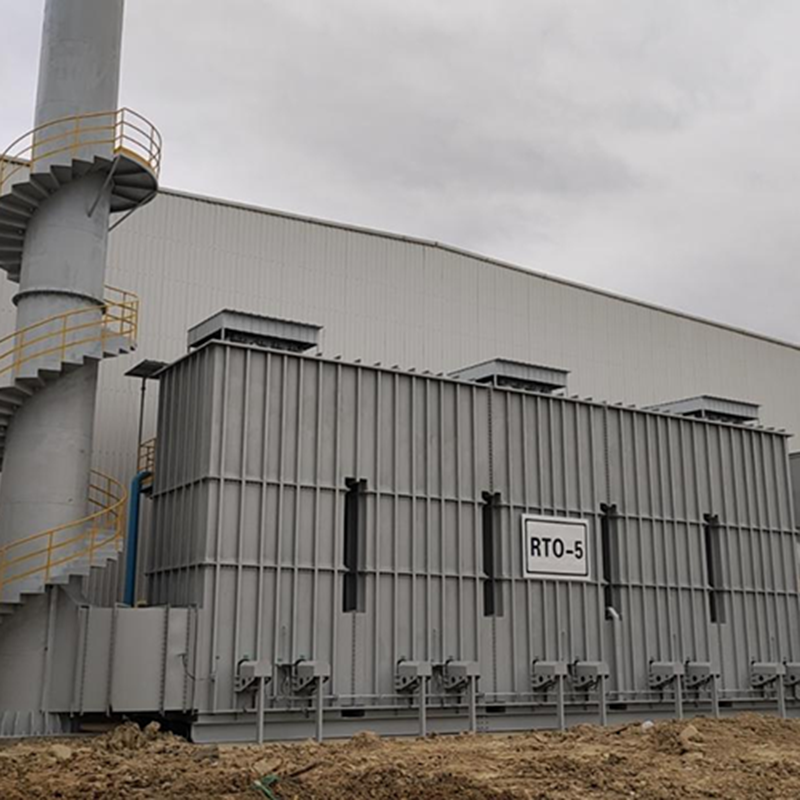
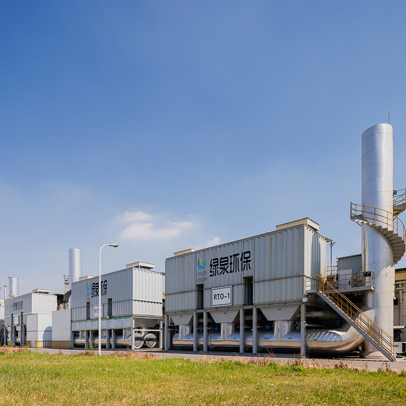
For plants with substantial VOC loads alongside chloride, a regenerative thermal oxidiser is often the central destruction unit, with the scrubber treating its exhaust. The equipment family below illustrates the type of heat storage oxidation system used upstream of the wet section in these trains.
Two design details are consistently overlooked. The first is the material selection for the region downstream of the oxidiser, where the gas is both hot and chloride-laden, and where cold spots create acid condensation. The second is the interaction between the scrubber and the oxidiser controls. A sudden change in scrubber pressure drop, for example after a nozzle plugs, changes the pressure balance across the whole train and can affect the oxidiser's fan curve and combustion stability. Interlocks that link the two systems, rather than treating them as independent packages, prevent a long list of nuisance shutdowns.
Plants that treat chlorinated streams should also plan for the disposal of scrubber blowdown. The purge stream carries sodium chloride, traces of other salts and, on some duties, organic carry-over. Sending it to a biological treatment plant without checking chloride tolerance, or to a neutralisation pit without a corrosion assessment, is a common and expensive oversight.
Key point: Treat the oxidiser and the HCl scrubber as one system with shared interlocks, because their pressure, temperature and control loops interact from the moment the first solvent is burned.
Most HCl scrubber performance loss happens gradually and invisibly. The stack remains visually clean, the fan current creeps upward, and the pH controller compensates for conditions it cannot see. A short, disciplined routine catches nearly all of this before a stack test does.
Two measurements deserve more attention than they usually receive. The first is the chloride concentration in the recirculating liquor, because it defines how much fresh make-up is needed to keep salts below saturation. The second is the differential pressure across the mist eliminator, which rises as deposits build and often indicates a wash system that has stopped working long before anyone notices the stack.
Key point: Chloride balance and mist eliminator differential pressure are the two early-warning indicators for an HCl scrubber, and both are cheap to monitor.
Field experience across many installations points to a short list of recurring problems. Each one has a design or specification fix, and almost all of them are cheaper to prevent than to repair.
A practical preventive measure is to ask for a written statement of the assumed droplet size distribution, inlet temperature range and chloride concentration, and then to compare those assumptions with the plant's actual process data. When the two do not match, the scrubber has effectively been designed for a different plant.
Key point: Nearly every HCl scrubber failure can be traced back to an assumption about droplets, temperature or chloride load that was never confirmed with the plant's own process data.
Emission limits for hydrogen chloride vary by country, industry and stack height. In China, the general air pollutant standard sets a hydrogen chloride concentration limit of 100 milligrams per cubic metre for many new sources, while specific sectors such as waste incineration apply considerably tighter values. Local permits, regional standards and industry-specific rules may be stricter again, and some plants face additional limits on visible plume, chloride deposition or odour.
Because limits are expressed as concentrations measured under defined conditions, the test method and the sampling location matter as much as the equipment. Hydrogen chloride in flue gas is commonly determined by ion chromatography after impinger sampling, and the presence of droplets can bias the result because droplet-borne chloride behaves differently from gaseous HCl during sampling. This is one reason why performance guarantees should state the test method, the sampling plane, the number of runs and the acceptance criteria rather than only a percentage removal figure.
A defensible guarantee typically covers guaranteed outlet concentration, guaranteed removal efficiency, the inlet conditions under which those figures apply, the pressure drop allowance, the reagent consumption allowance, and the consequences of deviation. It should also state what happens if the inlet conditions differ from those assumed, because that clause determines who pays when the plant expands production or changes a solvent.
Key point: A removal percentage without a defined test method, inlet condition range and sampling location is not a guarantee, it is a description.
Buyers comparing quotations from several manufacturers often find that the technical documents look similar while the actual equipment differs substantially. The questions below separate a designed system from a catalogue selection, and they apply equally to a direct manufacturer, a supplier working through partners, or a wholesaler providing replacement internals such as packing, nozzles and mist eliminator elements.
Two commercial points are worth negotiating explicitly. The first is accessibility: whether the packing can be inspected and partly replaced without dismantling the tower, and whether the mist eliminator can be removed through a manway. The second is documentation: whether the supplier will provide a full material certificate package, a corrosion assessment and a marked-up drawing set for future maintenance. Both cost little at the order stage and save a great deal later.
Key point: The strongest signal of a competent HCl scrubber supplier is a willingness to put inlet assumptions, velocity, pH control and pressure drop in writing before the order is placed.
Capital cost for an HCl scrubber is driven by gas flow, but not in a simple linear way. A larger cross section reduces velocity and pressure drop, which lowers fan power, while a taller tower or a second stage increases shell cost. The result is that several technically valid designs for the same duty can differ substantially in total installed cost, and comparing them requires looking beyond the equipment price.
Operating cost splits into three parts: reagent, electricity for the fan and pumps, and maintenance labour and spares. Reagent cost is usually the smallest of the three. A design that saves a few hundred kilograms of caustic each month but doubles fan power is rarely a good trade, and a design that saves capital by omitting adequate pH control will typically spend that saving within two years on repairs and rework.
Key point: Compare HCl scrubber options on five-year total cost, where fan energy, reagent and maintenance usually outweigh the difference in purchase price.
An HCl scrubber removes hydrogen chloride from an exhaust gas so that the stack concentration meets a permitted limit and the surrounding structure, ductwork and equipment are protected from acid attack. Typical applications include pickling lines, electroplating, pharmaceutical and chemical synthesis, incineration flue gas and the exhaust of thermal oxidisers burning chlorinated solvents.
Water alone will absorb HCl while the liquor remains dilute, but the sump acidifies quickly under continuous load and absorption efficiency falls once the pH drops below about 2. A small caustic dose holding the liquor at pH 8 to 9 makes performance far less sensitive to load changes and protects the shell from low-pH corrosion. Water-only operation suits very light, intermittent duties.
Start with the gas flow at operating temperature, the HCl concentration, the moisture content and the gas temperature. From there, the cross section is set by the chosen superficial velocity, the packing height is set by the transfer units required for the target outlet concentration, and the liquid to gas ratio is set by the absorption rate and dust load. If a supplier quotes only a diameter and a price, the design basis is missing.
A single packed stage with pH control typically achieves 95 to 99 percent removal on a clean, cool stream. Two stages with separate liquid loops can exceed 99 percent. Where fine mist or dust is present, a venturi or high-efficiency mist eliminator may be needed to reach higher figures. Actual performance depends on inlet conditions and on maintenance quality.
A visible plume usually comes from entrained droplets or from a saturated gas stream cooling above the stack exit. Droplet carry-over points to mist eliminator face velocity, a failed wash cycle or a distributor that is not covering the bed evenly. Saturated gas that condenses above the stack is a separate phenomenon and may need reheat rather than more caustic.
A setpoint between 8 and 9 works for most HCl duties. Below 7.5, acid slip increases and the risk of corrosion rises. Above about 10, caustic consumption climbs without a proportional efficiency gain, and the liquor begins absorbing carbon dioxide, which forms carbonate scaling on packing and nozzles.
Expect daily readings of pH, flow, pressure drop and fan current, weekly nozzle and wash system checks, monthly probe calibration and packing inspection, and an annual internal inspection of the shell, fasteners, fan and duct. The routine is not heavy, but skipping the pH calibration and the eliminator wash accounts for a large share of performance complaints.
No. Solvents such as dichloromethane or trichloroethylene must be destroyed by thermal or catalytic oxidation first, which produces HCl as a combustion product. The scrubber treats that HCl downstream. Some configurations also place a pre-scrubber ahead of the oxidiser to reduce the chloride load entering the hot section and protect refractory and catalyst.
Polypropylene and FRP with vinyl ester resin cover most shells, with PVC for cooler sections and PVDF or PTFE for high-temperature internals and linings. The critical selections are not the shell but the wet-dry boundary, the fan wheel, the pump and every fastener, which should all be specified in chloride-resistant grades.
It depends on where the chloride originates. If HCl is present in the raw stream, a pre-scrubber protects the hot section from chloride attack and by-product formation, and a post-scrubber polishes the residual. If HCl is generated by burning chlorinated compounds, only a post-scrubber is needed, usually with a quench or heat exchanger ahead of it to bring the gas down to a temperature the packing can tolerate.
Key point: Almost every FAQ above comes back to the same three variables, which are inlet condition accuracy, pH control and droplet removal.
If you are at the point of comparing designs or preparing a specification, the two resources below are a useful starting point. The first shows how the equipment is manufactured and assembled, which helps when you assess fabrication quality and inspection access. The second discusses flue gas cleaning on waste liquid incineration, a duty where hydrogen chloride control is closely tied to quench design and material selection.
See the production facility, machining capability and assembly arrangements behind VOCs abatement equipment, including the structural and material details that decide how an acid service system survives in the field.
A closer look at how incineration systems handle chloride-bearing waste streams and what the downstream cleaning train must remove, which is directly relevant to scrubber sizing and material selection.
An HCl scrubber is not a complicated machine, but it is unforgiving of assumptions that were never checked. Confirm the inlet temperature range, the droplet size distribution and the chloride load, insist on written design values for velocity, liquid to gas ratio and pH control, and specify materials for the wet-dry boundary and the small parts. That combination prevents the majority of problems that appear two or three years after commissioning.
Key point: Buy the design basis, not the tower, because a correctly documented HCl scrubber is the only one that can be maintained back to its guaranteed performance.
Overview Of Tower-Type RTO Regenerative Thermal Oxidizer (RTO) is an organic waste gas treatment equipment that combines high-temperature oxidation wi...
See Details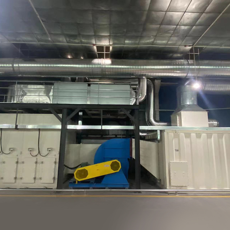
Overview Of Variable Freouency Zeolite Turntable Our company's zeolite concentration turntable uses a combination of zeolite modules, with a high zeol...
See Details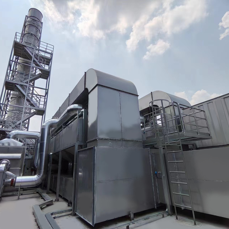
Overview of Activated Carbon Fiber Organic Solvent Purification Recovery Device The Activated Carbon Fiber Organic Solvent Purification Recovery Syste...
See Details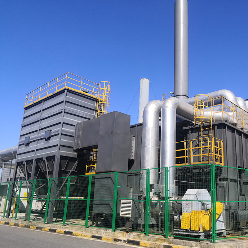
Concept Of Zeolite Wheel+RTO System Using zeolite wheel to adsorb organic waste gas, the low concentration and high air volume waste gas is concentrat...
See Details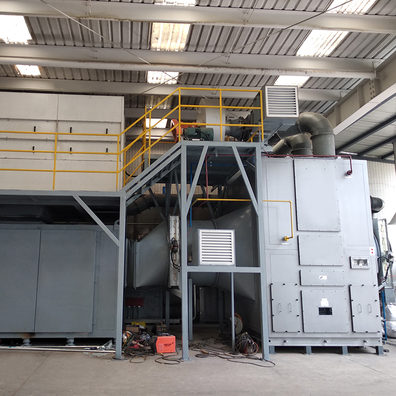
The Concept Of The Complete Set Of Equipment The purpose of employing rotary drum zeolite adsorption for organic waste gas is to concentrate low-conce...
See Details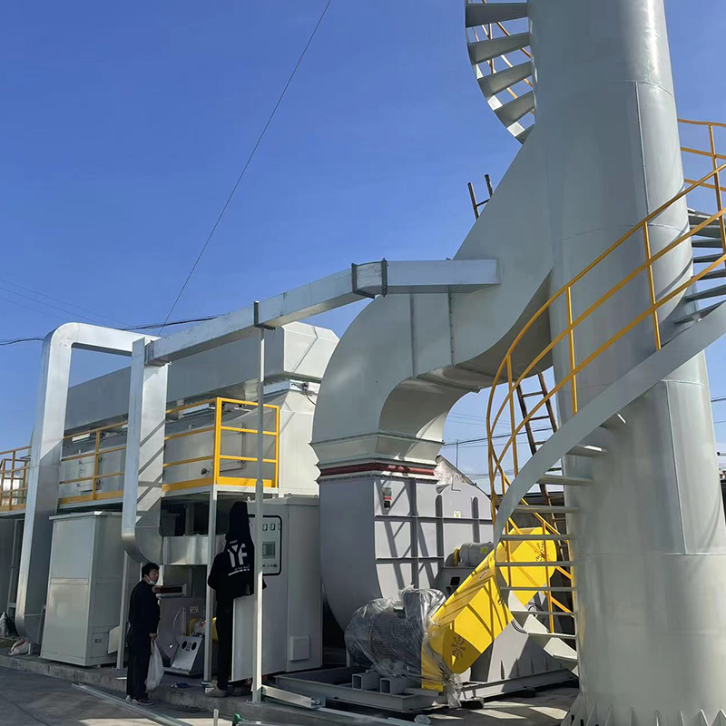
The VOC-CFT-CO Adsorption Catalytic Purification Equipment The VOC-CFT-CO adsorption catalytic purification equipment, consisting of fixed-bed honeyco...
See Details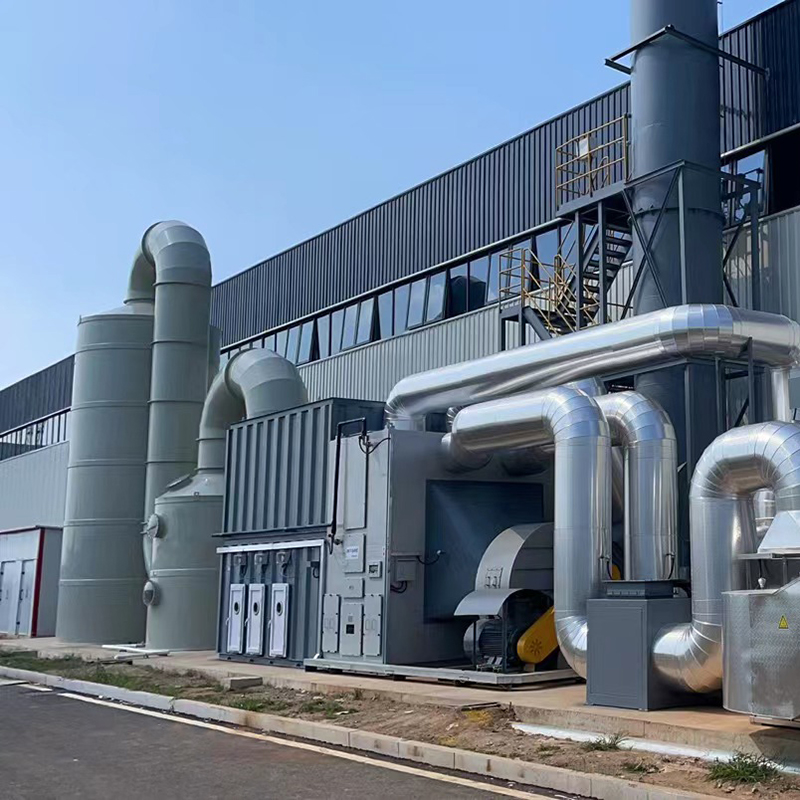
Concept Of Fixed Bed Zeolite + Catalytic Combustion As A Set Of Equipment The fixed bed zeolite + catalytic combustion device is suitable for the conc...
See Details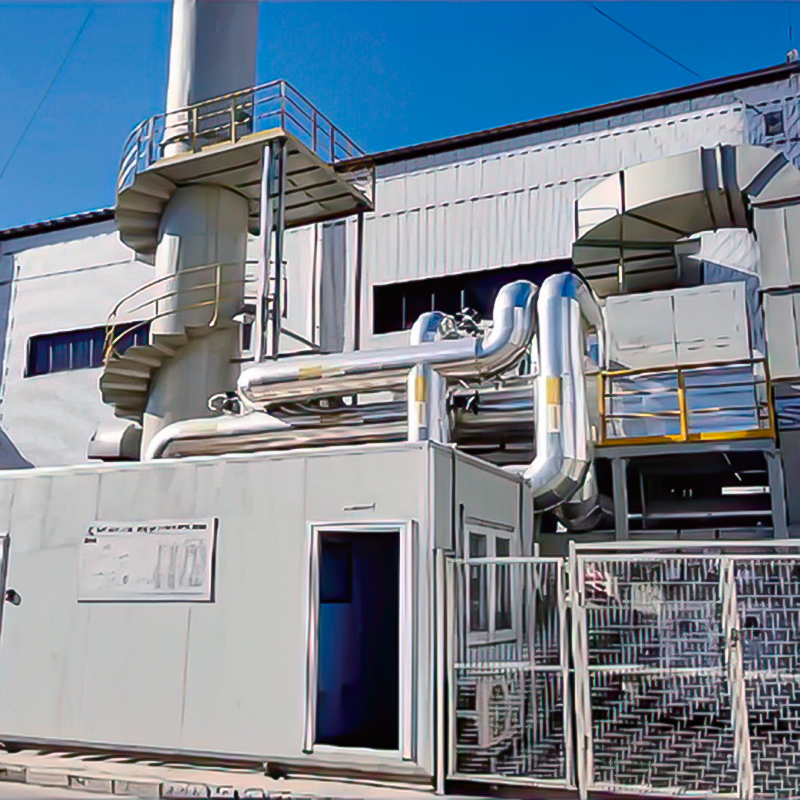
Concept Of Zeolite Rotary Wheel + Catalytic Combustion As A Set Of Equipment In the combined process of organic waste gas and waste gas treatment, the...
See Details
Overview The wet dust removal principle uses the process of capturing and separating dust particles in the gas phase by fully contacting gas-liquid tw...
See Details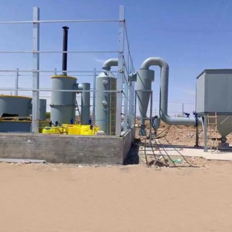
Overview Solid waste incineration furnaces are essential equipment in the management of solid waste, designed to transform waste materials into ash an...
See DetailsMOBILE
Product Manual

Copyright © Lv quan Environmental Protection Engineering Technology Co., Ltd. All Rights Reserved. Vocs Organic Waste Gas Treatment Engineering Equipment Manufacturer

