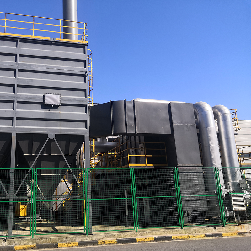
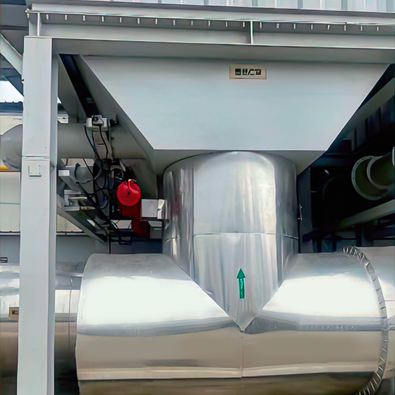
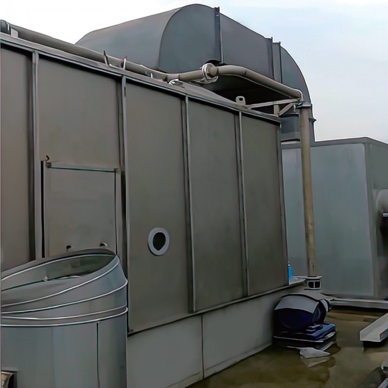
Organic waste gas treatment equipment is engineering equipment built to capture, concentrate, and either destroy or recover volatile organic compounds released during industrial production before those compounds reach the atmosphere. Core methods used across the industrial waste gas treatment field include adsorption, catalytic oxidation, regenerative thermal oxidation, condensation recovery, and pretreatment scrubbing, and a properly configured system typically reaches a removal efficiency between 90 percent and above 99 percent depending on pollutant concentration, airflow volume, and equipment configuration. This article explains how the equipment functions, which technology fits which production process, how to interpret common performance data, what routine operation requires, and what to look for when evaluating an organic waste gas treatment equipment factory as a long term technical partner.
Understanding Industrial Waste Gas Composition
Industrial waste gas is rarely a single pollutant stream. Depending on the manufacturing process, exhaust air can carry volatile organic compounds, particulate matter, oil mist, moisture, and in some cases odorous sulfur or nitrogen containing gases. The relative proportion of each component changes the way equipment must be designed, since a system optimized for dry solvent vapor will not perform the same way on a humid, particulate heavy stream.
Common categories of industrial waste gas and the pretreatment approach usually applied
Pollutant Type
Common Source
Typical Handling Method
Volatile Organic Compounds
Painting, printing, coating lines
Adsorption or oxidation
Particulate Matter
Sanding, cutting, powder handling
Filtration pretreatment
Oil Mist
Metal machining, lubrication
Mist separator pretreatment
Moisture Vapor
Washing, drying processes
Condensation or demister stage
Odorous Compounds
Rendering, chemical synthesis
Biofiltration or scrubbing
Because these components rarely appear alone, most industrial waste gas treatment systems are built as a sequence of stages rather than a single purification step. Pretreatment removes physical contaminants that would otherwise foul adsorption media or catalyst surfaces, while the main treatment stage addresses the gas phase organic load. Skipping proper pretreatment is one of the most common causes of premature equipment underperformance, since particulates and oil residue gradually block adsorption pores and reduce effective surface area.
Core VOCs Control Technologies Compared
Four technology families dominate current industrial waste gas treatment applications: activated carbon adsorption, catalytic oxidation, regenerative thermal oxidation, and biofiltration. Each has a distinct efficiency range, operating temperature, and suitable concentration band, as summarized in the chart below.
This bar chart compares approximate average removal efficiency percentages reported for four commonly used industrial waste gas treatment technologies. Activated carbon adsorption generally performs in the 90 to 98 percent range and works well for low to medium concentration streams with intermittent operation patterns typical of coating and printing lines. Catalytic oxidation performs in a similar band but requires a stable operating temperature window and is sensitive to catalyst poisoning from compounds such as silicone or certain sulfur bearing gases. Regenerative thermal oxidation, shown here with the highest average efficiency near 95 to 99 percent, is favored for larger continuous airflow volumes because its internal heat exchange ceramic bed keeps auxiliary energy input low relative to destruction performance. Biofiltration sits at a comparatively lower efficiency band and is typically applied to biodegradable, lower concentration odor streams rather than high concentration solvent vapor, which is why it appears more often in food processing or wastewater related applications. Reading these figures together helps a plant engineer shortlist technologies before requesting a detailed proposal from an organic waste gas treatment equipment factory.
Performance Behavior Over Operating Hours
Efficiency figures published for new equipment describe a starting point rather than a fixed constant. As adsorption media ages or ceramic beds accumulate residue, treatment efficiency gradually shifts, and understanding this pattern is important for setting realistic maintenance intervals.
This line chart illustrates a typical gradual decline pattern in adsorption bed removal efficiency across accumulated operating hours between media servicing cycles. Efficiency usually starts near its rated value shortly after installation or media replacement, and remains relatively stable for the first several hundred hours of operation under normal loading conditions. As operating hours increase, adsorption capacity slowly decreases due to progressive pore saturation, and the curve begins to slope downward at a faster rate once the media approaches its practical service life. This behavior explains why many facilities schedule media inspection or replacement based on cumulative operating hours rather than waiting for a visible performance complaint. Tracking this curve over successive service cycles also helps identify whether upstream pretreatment is functioning correctly, since an unusually steep decline often points to particulate or oil mist bypassing the pretreatment stage. Recording this data consistently gives engineering staff an objective basis for maintenance planning rather than relying on estimation alone.
Where Industrial Waste Gas Originates
Industrial waste gas is generated across a wide range of manufacturing sectors, and understanding the relative contribution of each sector helps explain why equipment design varies so much between industries.
This donut chart illustrates a typical distribution of industrial waste gas generation across manufacturing sectors. Chemical and petrochemical processing tends to represent the largest share due to solvent handling and reaction off gas that must be continuously vented. Coating and printing operations, including automotive and coil coating lines, form a substantial second segment because solvent based paints and inks release VOCs continuously during application and drying stages. Pharmaceutical manufacturing contributes a meaningful share linked to solvent recovery steps and reactor venting during batch production. Electronics assembly, furniture and woodworking, and other smaller manufacturing categories make up the remaining portion, each carrying its own gas composition and concentration profile that influences equipment sizing. This kind of breakdown is one reason an organic waste gas treatment equipment factory usually designs each project individually rather than offering a single standard configuration for every client.
Matching Treatment Technology To Industry
Because gas composition differs so widely between sectors, treatment technology suitability also varies. The table below presents a general suitability pattern based on common industry practice, shown as a shaded matrix rather than a simple list.
General suitability pattern of treatment technology by manufacturing sector
Coating
Chemical
Pharma
Electronics
Adsorption
High
Medium
High
High
Catalytic Oxidation
Medium
High
Medium
Medium
RTO
High
High
Medium
Low
Biofiltration
Low
Low
Low
Low
Coating lines and chemical processes generally support the widest range of technology options because their airflow and concentration profiles are well documented across the industry, while electronics assembly gas is usually lower concentration and lower temperature tolerant, which limits regenerative thermal oxidation to specific higher load situations rather than routine application.
Comparing Technology Attributes Side By Side
Beyond removal efficiency alone, engineers commonly weigh four additional attributes when comparing technologies: energy input requirement, tolerance to concentration fluctuation, media or catalyst service life, and suitability for continuous operation.
This radar chart compares regenerative thermal oxidation, shown in the outer yellow shape, against catalytic oxidation, shown in the inner orange shape, across four practical attributes rather than efficiency alone. Regenerative thermal oxidation typically scores higher on continuous operation fit and fluctuation tolerance because its ceramic bed can absorb variation in concentration without immediate performance loss. Catalytic oxidation often scores closer on raw removal efficiency but shows comparatively more sensitivity to concentration fluctuation and requires closer monitoring of catalyst condition over its service life. Media life scoring reflects how long the core treatment component typically functions before requiring replacement or refurbishment under normal industrial duty cycles. Viewing these attributes together, rather than efficiency in isolation, gives a more complete picture when comparing options offered by an organic waste gas treatment equipment company for a specific production environment.
Thermal Efficiency And Energy Recovery
Regenerative thermal oxidizers recover a large portion of combustion heat through ceramic media beds, which significantly reduces auxiliary fuel consumption during continuous operation.
This gauge chart represents a typical thermal energy recovery efficiency reported for well maintained regenerative thermal oxidation systems, often reaching a range near 95 percent under stable operating conditions according to general industry engineering references. Higher heat recovery directly reduces the amount of supplemental fuel needed to sustain the combustion chamber temperature during continuous operation. This efficiency level depends on ceramic media condition, valve switching sequence accuracy, and airflow balance across the individual chambers, so routine inspection is necessary to sustain the figure over years of service. A gradual decline in recovery efficiency is often the first indicator that ceramic media cleaning or valve seal replacement is due before a larger performance issue develops. Facilities that track this figure over time can use it as an early operational health indicator rather than waiting for a full performance test to reveal a problem.
Airflow Composition Before And After Pretreatment
Pretreatment changes the proportion of contaminants entering the main treatment stage. The stacked comparison below reflects a representative shift in composition for a coating line exhaust stream.
This stacked bar comparison shows how the proportion of particulate matter, moisture, and volatile organic compounds within an exhaust stream shifts once it passes through a pretreatment stage. Before pretreatment, particulate matter and moisture together often occupy a substantial share of the airflow composition alongside the organic compound load. After pretreatment, particulate content and excess moisture are largely removed, allowing the remaining airflow entering the adsorption or oxidation stage to consist predominantly of the organic compound fraction that the main treatment technology is specifically designed to address. This shift matters because adsorption media and catalyst surfaces perform more consistently when particulate fouling and moisture interference are minimized ahead of time. Facilities that skip or under design pretreatment often see faster media degradation even when the main treatment unit itself is correctly sized. This comparison illustrates why pretreatment is treated as a core design step rather than an optional add on within a complete industrial waste gas treatment system.
How To Select Organic Waste Gas Treatment Equipment
Choosing equipment from an organic waste gas treatment equipment factory involves several practical evaluation steps rather than relying on a single specification sheet.
Confirm actual airflow volume and concentration through on site measurement rather than nameplate assumptions.
Identify whether the gas stream is continuous or intermittent, since this affects adsorption bed cycling design.
Check compatibility between the target compounds and catalyst or activated carbon media selected.
Review ductwork layout and pressure drop across the full system, not only the treatment unit itself.
Ask for reference installations in a similar industry with comparable gas characteristics.
Evaluate instrumentation options for monitoring pressure drop, temperature, and outlet concentration over time.
Lv quan Environmental Protection Engineering Technology Co., Ltd., located in Gaoyou City, Yangzhou Province, has focused on this type of project specific design work for more than a decade, covering adsorption, incineration, recovery, and pretreatment stages for VOCs organic waste gas treatment across vehicle manufacturing, coil coating, petrochemical, pharmaceutical, electronics, machinery, printing, and furniture building materials industries.
Inside The Equipment: Structural Overview
A combined organic waste gas treatment system generally follows a sequential internal layout, illustrated schematically below.
This isometric style schematic shows the general internal sequence of a combined organic waste gas treatment system, moving from left to right through intake ductwork, pretreatment, adsorption or concentration, and finally an oxidation chamber before clean air release. Waste gas first enters through the intake section, where fans establish negative pressure to draw exhaust from the production line into the ductwork network. The pretreatment stage removes particulates, oil mist, or excess moisture that could otherwise reduce adsorption media lifespan, as discussed in the earlier composition comparison. The adsorption section then concentrates VOCs from a large low concentration airflow into a smaller high concentration stream through cyclical bed switching between adsorption and desorption modes. Finally the oxidation chamber destroys the concentrated stream at controlled temperature before the treated air passes through the exhaust stack, and this staged sequence is common across many industrial waste gas treatment installations regardless of exact equipment brand or manufacturer.
Operation And Maintenance Considerations
Consistent performance from waste gas treatment equipment depends on scheduled maintenance rather than one time installation quality alone. Adsorption media requires periodic inspection for saturation and physical degradation, while valve seals and ceramic beds in thermal oxidation units need regular checks for leakage and thermal fatigue.
Daily Checks
Visual inspection of gauges, fan operation, and stack discharge appearance to catch obvious irregularities early.
Weekly Checks
Pressure drop readings across major stages compared against baseline values recorded at commissioning.
Monthly Checks
Valve seal condition, ductwork joints, and instrumentation calibration verification across the full system.
Annual Review
Comprehensive media or catalyst condition assessment together with a full efficiency verification test.
Operators typically monitor pressure drop across the system, exhaust temperature at the stack, and periodic VOC concentration readings before and after treatment. A rising pressure drop across an adsorption bed is often the earliest sign that media replacement should be scheduled, allowing the issue to be addressed before efficiency drops noticeably during production.
Industry Direction For Industrial Waste Gas Control
Regulatory attention on VOCs continues to increase across manufacturing regions because these compounds contribute to ground level ozone and secondary particulate formation, a relationship documented in air quality background materials published by agencies such as the United States Environmental Protection Agency. This has pushed many facilities toward combined technology systems that pair adsorption concentration with thermal destruction, since this combination generally supports both energy efficiency and consistent removal performance across variable production schedules. Facilities upgrading older single stage systems increasingly request integrated pretreatment and monitoring instrumentation as part of the same project, reflecting a broader shift toward system level rather than component level thinking in industrial waste gas treatment planning. Interest has also grown in remote monitoring capability, allowing engineering teams to review pressure drop, temperature, and concentration trends without needing a technician present at the site continuously, which supports the kind of proactive maintenance schedule described in the previous section.
About Lv Quan Environmental Protection Engineering Technology Co., Ltd.
Lv quan Environmental Protection Engineering Technology Co., Ltd. is based in Gaoyou City, Yangzhou Province, often referred to as the northern gateway of Jiangsu. The company was established by a team with more than 30 years of combined experience in VOCs equipment design and manufacturing, and operates with a registered capital of 22 million yuan and a total asset value approaching 60 million yuan. Production facilities span 9,800 square meters and include over 200 sets of mechanical processing equipment, supported by a workforce of 120 staff members.
As an organic waste gas treatment equipment factory, the company concentrates on the environmental protection design and manufacturing of VOCs organic waste gas treatment systems covering adsorption, incineration, recovery, and pretreatment. Its product portfolio serves vehicle manufacturing, coil coating, petrochemical, pharmaceutical, electronics, machinery, printing, and furniture building materials industries. The Lv Quan brand has absorbed and refined established adsorption and incineration manufacturing approaches over time, working to bring product safety and stability closer to the level of established domestic peers within the organic waste gas treatment equipment company category.
Frequently Asked Questions
What does industrial waste gas treatment equipment actually remove
It primarily targets volatile organic compounds along with associated particulates, oil mist, and in some cases odorous gases generated during production processes such as coating, printing, or chemical synthesis.
How is treatment technology chosen for a specific facility
Selection depends on measured airflow volume, VOC concentration, whether the process runs continuously or intermittently, and compatibility with the specific compounds present, which is why on site gas testing usually precedes final equipment design.
Can adsorption and thermal oxidation be combined in one system
Yes, combining adsorption concentration with thermal oxidation destruction is a common configuration for lower concentration, higher volume gas streams, since it improves overall energy efficiency compared with treating dilute gas directly with heat alone.
How often does adsorption media need attention
This depends on gas concentration and operating hours, but rising pressure drop across the bed or declining outlet concentration performance are the usual indicators that inspection or replacement is due.
Why does pretreatment matter if the main unit already treats VOCs
Pretreatment removes particulates, oil mist, and excess moisture that would otherwise foul adsorption media or catalyst surfaces, and skipping this stage often leads to faster degradation of the main treatment component.
What industries commonly require this type of equipment
Vehicle manufacturing, coil coating, petrochemical processing, pharmaceutical production, electronics assembly, machinery manufacturing, printing, and furniture or building materials production are among the sectors most frequently applying industrial waste gas treatment systems.
Overview
Direct combustion high-temperature incineration equipment, abbreviated as TO, utilizes the heat generated by the combustion of auxiliary fuel...
Overview
Catalytic combustion is a purification method that uses catalysts to oxidize and decompose combustible substances in exhaust gas at low tempe...
Overview
The VOC-ACA series organic gas particle carbon purification and recovery equipment is used for the absorption, recovery, and reuse of organic...
Concept Of Zeolite Wheel+RTO System
Using zeolite wheel to adsorb organic waste gas, the low concentration and high air volume waste gas is concentrat...
The Concept Of The Complete Set Of Equipment
The purpose of employing rotary drum zeolite adsorption for organic waste gas is to concentrate low-conce...
The Concept Of Zeolite Wheel+ Direct Combustion High-Temperature Incineration Equipment
The purpose of employing rotary drum zeolite adsorption for or...
Purpose
Mainly used for proportional ventilation of high-temperature flue gas. lt is widely used in places where leak rate requirements are not high, ...
Overview
The wet dust removal principle uses the process of capturing and separating dust particles in the gas phase by fully contacting gas-liquid tw...


 English
 русский
 Français
 Español
 عربى
عربى