

 English
 русский
 Français
 Español
 عربى
عربى
LQ-RTO Heat-storage high-temperature incineration equipment
Cat:Equipment
Overview Of Tower-Type RTO Regenerative Thermal Oxidizer (RTO) is an organic waste gas treatment equipment that combines high-temperature oxidation wi...
See Details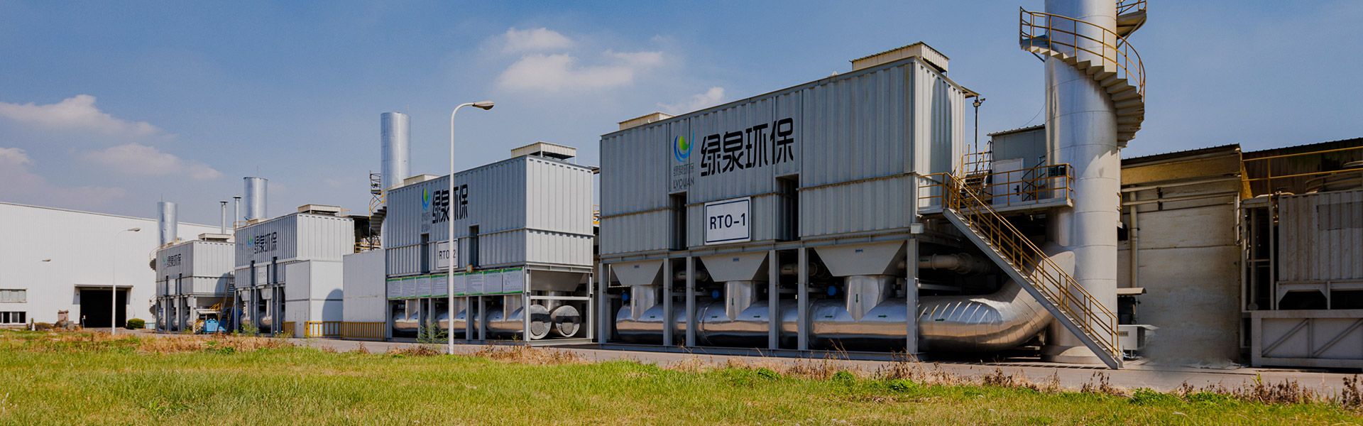
Content
During a commissioning test at a coil coating plant, the regenerative thermal oxidizer held VOCs emission below the required limit, but the nitrogen oxide reading suddenly became the bottleneck. The plant owner had never included DeNOx in the original scope because the previous finishing line did not involve high-temperature combustion. That same scene repeats in chemical, pharmaceutical, painting, printing, and metal manufacturing workshops where VOCs abatement equipment is already operating. A DeNOx strategy is not an afterthought; it is part of the emission control chain that keeps a facility inside its permit limits and avoids unexpected penalties.
This article discusses DeNOx in practical engineering terms: what it means, how nitrogen oxides form inside industrial exhaust systems, where DeNOx connects with RTO and other thermal oxidizers, and how a buyer should select, design, operate, and maintain the equipment. The goal is to give plant engineers, EHS managers, procurement teams, and company owners a clear basis for making decisions before they commit budget to a compliance project.
You will also find comparisons between SCR and SNCR, maintenance guidance, cost factors, and a direct view of how DeNOx and VOCs treatment equipment work together in one coordinated system.
DeNOx is the removal of nitrogen oxides, commonly written as NO and NO₂, from combustion flue gas or process exhaust. The term comes from denitrogenation and is widely used by emission-control engineers to describe any system that reduces NOx before it reaches the stack. Nitrogen oxides are formed when nitrogen and oxygen react at high temperature or when nitrogen compounds inside fuels are oxidized during combustion.
Industrial emission standards in China and many other markets set strict NOx limits for boilers, thermal oxidizers, waste incinerators, and many manufacturing processes. Depending on local requirements, a plant may need to keep NOx emissions below 80 mg/m³, 100 mg/m³, or even 50 mg/m³. If only VOCs treatment is installed, NOx is easy to overlook because the initial equipment bid usually focuses on hydrocarbons, not combustion by-products.
The formation of NOx is not uniform. In practice, engineers separate NOx sources into three paths:
Because VOCs treatment often relies on combustion, a facility may reduce hydrocarbon emissions while unintentionally creating additional NOx. Table 1 gives a fast comparison of the three formation paths and the usual control direction for each.
| Table 1: Common NOx formation paths in industrial processes and typical control measures | ||
| Formation path | Typical condition | Effective control direction |
| Thermal NOx | High temperature and enough free oxygen | Lower peak temperature, staged combustion, flue gas recirculation |
| Fuel NOx | Nitrogen compounds in liquid or solid fuel | Change fuel type, use low-nitrogen fuel, optimize burner air ratio |
| Prompt NOx | Short flame zone of gas combustors | Burner design, air staging, fuel staging |
The practical conclusion is that DeNOx planning has to begin at the same time as VOCs equipment selection. If the RTO, catalytic oxidizer, or direct-fired oxidizer is chosen without considering NOx, the project may face expensive retrofits after the first compliance test.
Key insight: DeNOx should be part of the initial system design, not a later correction, because nitrogen oxide control affects oxidizer temperature selection, burner configuration, and downstream equipment space.
Regenerative thermal oxidizers typically operate at 760–850°C in the combustion chamber. That temperature is high enough to destroy VOCs quickly, but it is also a zone where thermal NOx can form. When a plant burns natural gas, the main concern is usually thermal NOx from the burner. If the exhaust also contains solvent vapors with nitrogen compounds, fuel NOx can become an additional challenge.
For a facility with a moderate NOx limit, the first improvement is combustion optimization. Low-NOx burners, staged combustion, and flue gas recirculation can reduce NOx formation at the source. These measures are often included in a modern RTO design and can keep NOx within typical industrial limits without adding a separate downstream system.
However, some projects face tighter requirements. A local regulation may demand a NOx limit that a thermal oxidizer alone cannot reliably meet, especially when the process has unstable solvent load or frequent start-stop cycles. In that case, the plant needs a dedicated DeNOx stage such as SCR or SNCR.
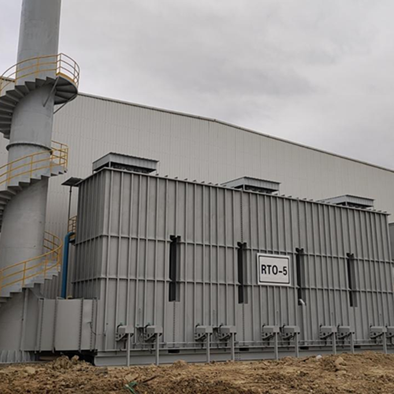 LQ-RTO Regenerative Thermal Oxidizer with Ceramic Heat StorageThis RTO uses ceramic heat storage to reach 95% heat recovery and can self-sustain at inlet concentrations of 1500–2000 mg/m³. It suits plants needing stable combustion before adding a DeNOx stage.View Product →
For plants choosing VOCs combustion equipment, the selection of the oxidizer itself is still central. An RTO with a stable ceramic heat-exchange bed, balanced air distribution, and a controllable burner reduces fuel consumption and creates a steady temperature profile that is easier to integrate with a DeNOx unit. A simple way to think about it is that the RTO takes care of the carbon, while DeNOx takes care of the nitrogen; both must work inside the same emission budget.
Catalytic oxidizers operate at lower temperatures, typically 300–450°C, so they generate less thermal NOx than direct-fired or regenerative thermal oxidizers. This is one reason plants with stringent NOx limits sometimes prefer RCO or catalytic combustion for medium-concentration VOCs. Yet catalysts introduce another sensitivity: sulfur, phosphorus, silicon, or heavy metal compounds can poison the oxidation catalyst, so the upstream waste-gas composition needs to be checked carefully.
Key insight: If your NOx limit is strict enough to demand SCR or SNCR, you must plan the oxidizer outlet temperature, flue-gas space, and stack location together with the DeNOx supplier so that the two systems fit physically and thermally.
Selective catalytic reduction is the most widely used DeNOx process in industrial emission control. SCR injects ammonia or urea into the flue gas stream and passes the mixture through a catalyst. The catalyst allows NOx to react with the reducing agent at a relatively low temperature, usually 250–420°C depending on the catalyst formulation. Because the reaction is selective, the reagent attacks nitrogen oxides rather than being consumed by oxygen.
Selective non-catalytic reduction works without a catalyst. The reagent is sprayed directly into a high-temperature zone, typically between 850°C and 1,100°C, where urea or ammonia decomposes and reacts with NOx. SNCR is cheaper to install than SCR, but its efficiency is lower and its temperature window is narrower. If the gas temperature drops too low, the reaction becomes slow; if it rises too high, ammonia can oxidize back into NOx.
For smaller plants, wet absorption and dry adsorption systems can also reduce NOx, but they tend to have higher reagent consumption and create wastewater or spent-solid disposal issues. Combustion control is not a removal technology; it prevents formation before it happens, which is why it should be considered a complementary method rather than a full DeNOx system.
Table 2 summarizes the main process options that a plant engineer will normally evaluate.
| Table 2: Comparison of typical DeNOx technologies for industrial waste gas | ||||
| Technology | Reagent or mechanism | Typical temperature window | Usual NOx reduction | Main consideration |
| SCR | Ammonia or urea with catalyst | 250–420°C | 80–95% | Catalyst cost, catalyst lifetime, ammonia slip |
| SNCR | Ammonia or urea, no catalyst | 850–1,100°C | 40–70% | Temperature control, reagent mixing |
| Wet absorption | Alkaline or oxidizing solution | Below 80°C | 60–85% | Wastewater treatment, chemical handling |
| Dry adsorption | Activated carbon or molecular sieve | 20–80°C | 50–75% | Adsorbent saturation, disposal, coexisting gases |
| Combustion optimization | Low-NOx burner, staging, recirculation | Inside combustion zone | 30–50% | Burner design, not applicable as standalone removal |
To help visualize the differences, the following horizontal bar chart shows the common NOx removal ranges for five approaches. These numbers are not fixed promises; they are typical design ranges seen in practical industrial applications.
The chart shows a clear hierarchy: SCR offers the highest removal range, which is why it is the most common choice when regulators demand very low NOx concentrations or when the plant expects long-term tightening. SNCR still has a useful role because it costs less and is easier to retrofit, but its upper limit is normally below 75%. Wet absorption and dry adsorption are applied where the flue gas volume is small, the temperature is already low, or the plant needs to handle other pollutants at the same time. Combustion control never achieves a very high removal percentage by itself, so it should be treated as a supporting measure that lowers the inlet load for a downstream DeNOx system.
For a facility with an RTO, the integration path depends on where the DeNOx system is placed. The RTO outlet temperature is usually below 200°C after heat recovery, which is too low for SCR and far below the SNCR temperature window. Therefore, an SCR unit is often placed after a separate reheating section, or the SCR catalyst is installed in a section of the flue where the gas temperature is still within the operating window. SNCR is more suitable inside a high-temperature chamber, such as the combustion zone of a boiler, incinerator, or thermal oxidizer before heat recovery. This temperature difference determines which technology is realistic for a given site.
Another important factor is ammonia slip. SCR systems normally keep slip below 3–5 ppm when well maintained; SNCR can produce higher slip because the reagent has to be mixed into a large hot gas volume without a catalyst to promote the reaction. Ammonia slip not only wastes reagent but can also create ammonium sulfate deposits when sulfur oxides are present, which leads to blocking on downstream heat exchangers and ducts. A complete DeNOx assessment has to examine the concentration of SO₂ and other acidic gases before selecting a reagent and injection system.
The final choice is therefore based on efficiency target, temperature profile, space, reagent availability, existing process equipment, and operating budget. No single DeNOx technology is universally superior; each one has an optimum range of gas flow, temperature, and emission requirement.
Key insight: SCR is the highest-removal DeNOx technology, but it only works efficiently when the flue-gas temperature matches the catalyst window; otherwise, you will spend extra money on reheating and catalyst management.
Many industrial processes generate both VOCs and nitrogen oxides. Paint booths, dryers, flexographic printing machines, chemical reactors, and rubber processing lines can emit volatile organic compounds, while boilers, thermal oxidizers, and some drying burners create NOx at the same time. If a plant controls only VOCs, the NOx source remains untreated; if it controls only NOx, the carbon-bearing pollutants still exceed their own limits. The practical answer is a coordinated train of treatment units rather than one magical machine.
A complete integrated flow often includes gas cooling or pre-treatment, adsorption concentration, catalytic or thermal oxidation, heat recovery, and a DeNOx stage. In high-volume, low-concentration VOCs streams, a zeolite wheel concentrator is frequently used to adsorb hydrocarbons and then desorb them into a small-volume, high-concentration gas stream, which is sent to a smaller oxidizer. This saves fuel and keeps the oxidizer footprint more compact, while also giving the plant a well-defined exhaust flow for NOx control.
The site offers purpose-built integrated VOCs treatment systems that combine adsorption, desorption, catalytic oxidation, and safety monitoring into one engineered package. Such a system is designed to effectively treat organic waste gas from printing, coating, furniture, chemical, and similar production lines. From a DeNOx perspective, the advantage of a packaged system is that the oxidizer inlet conditions, temperature profile, and control logic are designed together, which reduces the risk of downstream temperature mismatch when a DeNOx unit must be added.
For plants that need to handle very low-concentration waste gas, a zeolite concentrator followed by regenerative thermal oxidation is a well-established configuration. The concentrator reduces the air volume, the RTO destroys the VOCs, and the remaining combustion gases can be polished by a DeNOx system if required by permit conditions.
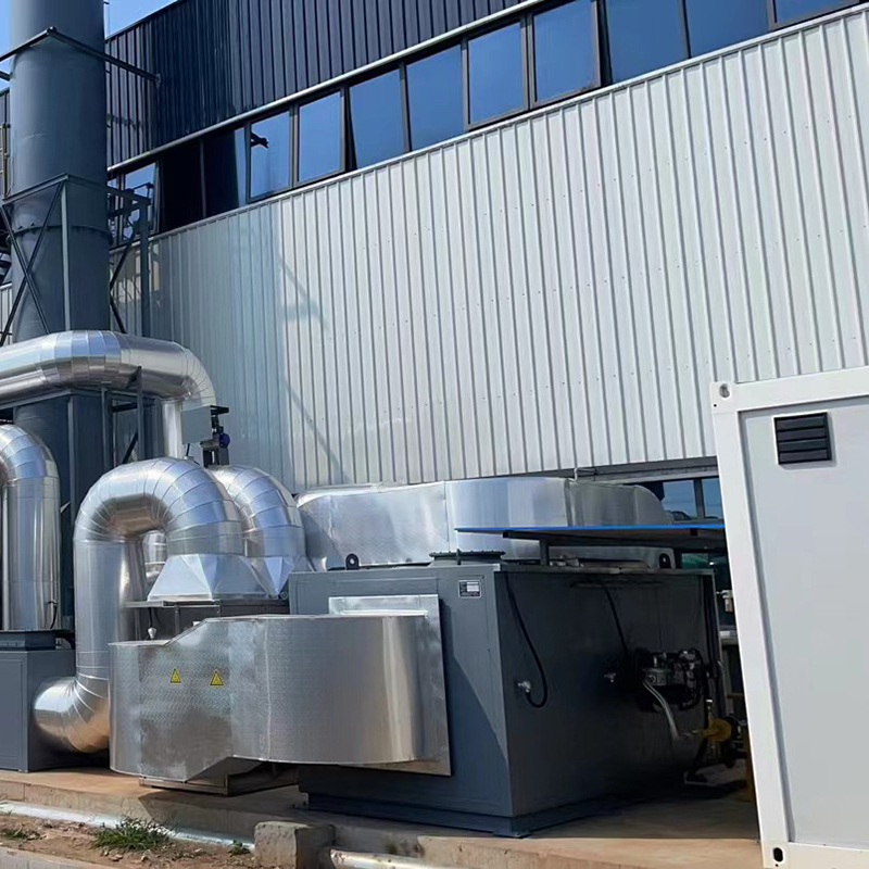 Zeolite Concentrator Combined with Regenerative Thermal OxidizerThis integrated system concentrates low-concentration VOCs before RTO destruction, reducing air volume and fuel demand. It is ideal for projects that may later require a DeNOx polish to meet tight NOx limits.View Product →
The layout decision is usually made during the basic engineering phase. If the NOx requirement is known early, the project team can enlarge the equipment room, leave a straight duct section for reagent injection and catalyst modules, and design enough access space for maintenance. If the DeNOx system is introduced after the RTO is already installed, the plant may need to rearrange ducts, add a reheater, or find a place to insert a catalyst housing. Those changes are possible, but they increase both cost and downtime.
| Table 3: Standalone emission control versus coordinated DeNOx and VOCs design | |
| Standalone design | Coordinated design |
| Each regulated pollutant is treated by an independent supplier. The RTO supplier offers a burner; the DeNOx vendor supplies an SCR skid. Interface issues include temperature mismatch, missing duct space, conflicting control logic, and separate maintenance schedules. | VOCs oxidation and DeNOx are included in the same overall system design, with shared sensors, controlled transitions between operating states, and a stack that is treated as a single emission point. This produces fewer shutdowns and simpler compliance reporting. |
An integrated approach also improves startup behavior. During a cold start, a VOCs oxidizer may need time to reach temperature; during that window the catalyst or reagent system should not be operated until the correct temperature range is reached. If the two pieces of equipment are controlled separately, the plant operator has to coordinate the interlocks manually. When they are designed as one system, the PLC logic can manage the sequencing automatically.
Key insight: The most economical way to treat VOCs and NOx in one facility is to design the entire emission-control train together, because DeNOx performance depends heavily on the temperature, position, and control strategy of the VOCs oxidizer.
DeNOx projects are usually purchased by a plant owner, an EPC contractor, or a mechanical engineering company on behalf of the end user. Because the technical risk is high and the consequences of a failed acceptance test are serious, the buyer should evaluate the manufacturer or supplier by engineering capability, not by price alone. A serious DeNOx supplier will ask about fuel composition, oxidizer operating temperature, flue-gas flow, dust load, sulfur content, and the actual NOx target; a vague quotation that skips these details often leads to performance problems later.
If the DeNOx system is being integrated into a VOCs abatement project, the easiest route is to work with a manufacturer that understands both sides of the problem. The company behind this article has designed and built VOCs treatment equipment for more than ten years and supplies RTO, RCO, catalytic combustion, zeolite concentrator, and adsorption recovery systems for coating, petrochemical, pharmaceutical, electronics, printing, and other industries. Its manufacturing facility covers production, assembly, and in-house quality control, which gives the customer a single point of responsibility for mechanical fabrication and system delivery. Its company certificates include environmental engineering qualifications and ISO management system certifications, reducing the risk of supplier non-compliance.
When comparing different suppliers, the buyer should treat DeNOx efficiency promises as a starting point, not a guarantee. The real test is whether the supplier can control temperature, reagent dosage, mixing, and monitoring under field conditions. A high theoretical removal rate means nothing if the injection grid creates uneven distribution or if the catalyst is oversized for the actual gas velocity.
When the DeNOx project is treated as a long-term operating asset, the annual operating cost is often more important than the initial capital cost. A cheap SNCR system that fails to meet a strict NOx limit can force the plant to add SCR later, wasting the original investment. A properly configured SCR system usually gives a stable result for five to ten years if the catalyst is monitored and maintained.
Key insight: The purchasing decision should be based on proven design data and lifecycle cost, not on a theoretical efficiency curve, because the difference between a smooth startup and a long commissioning delay often comes from the quality of engineering integration.
The catalyst is the most sensitive component in an SCR DeNOx system. A well-maintained catalyst can meet its design removal efficiency for years, but operating conditions that damage it can cause a sudden performance drop. The most common problems are poisoning, thermal sintering, dust deposition, and mechanical erosion. Each failure mode has a different root cause, so maintenance staff should build the inspection plan around the actual flue-gas composition and plant operation.
| Table 4: DeNOx catalyst degradation factors, effects, and preventive actions | ||
| Degradation factor | Effect on catalyst or system | Preventive action |
| Sulfur poisoning | Reduced active sites, ammonium sulfate deposits | Control inlet SO₂, maintain temperature above the dew point |
| Phosphorus and heavy metals | Permanent catalyst deactivation | Improve upstream filtration for phosphorus or metal compounds |
| Dust and particulate blocking | High pressure drop, reduced contact with NOx | Install dust removal, soot blowing, or a protective pre-filter |
| Thermal sintering | Decreased surface area, lower activity | Stay inside the catalyst temperature limit, avoid rapid overheat |
| Ammonia injection imbalance | Localized slip or uneven NOx removal | Periodically check injection lance wear and verify flow distribution |
Daily DeNOx maintenance starts with the reagent supply system. Ammonia flow must be adjusted when the combustion load changes, and the injection pressure should be checked for blocked nozzles. In an SNCR system, poor atomization is one of the first signs of trouble; it creates larger droplets, shorter reaction time, and higher ammonia slip. In an SCR system, the reagent evaporation and mixing distance must be respected, so any modification to the duct layout should be reviewed by the original DeNOx manufacturer.
Temperature records should be checked against the catalyst supplier’s recommended window. SCR catalysts become active only above a certain temperature; below that, the reaction rate falls quickly. If the plant often runs at partial load, the flue-gas temperature may drop too low for effective DeNOx. In that case, the operational fix could be to redirect a portion of hot gas, reduce the excess air, or temporarily bypass a heat-recovery section during startup.
Regular measurement is essential. A plant should track inlet NOx, outlet NOx, reagent flow, flue-gas temperature, pressure drop, and ammonia slip. When pressure drop increases above the baseline by 20–30%, the catalyst or heat exchanger is probably accumulating dust. When ammonia slip starts to rise without any change in reagent flow, the catalyst may be losing activity or the gas distribution may be uneven.
For plants that already operate VOCs treatment equipment, maintenance scheduling can be combined. The oxidizer burner should be checked at the same time as the DeNOx injection grid, the catalyst module can be replaced during a planned shutdown of the RTO, and the continuous emission monitoring system can be calibrated on a shared schedule. This reduces downtime and avoids repeated crew mobilization.
Key insight: DeNOx performance is not only a design issue; it is also an operating discipline, and the plants that keep running records of temperature, reagent, pressure drop, and ammonia slip are the ones that pass environmental inspections with fewer surprises.
DeNOx refers to the removal of nitrogen oxides from flue gas or process exhaust. The word is commonly used for any equipment or method that reduces NO and NO₂ emissions, including combustion optimization, SCR, SNCR, wet absorption, and dry adsorption.
You need DeNOx if your local emission permit sets a NOx limit and your plant cannot meet that limit using combustion control alone. Facilities with boilers, thermal oxidizers, waste incinerators, glass furnaces, and certain chemical processes are the most likely to require a dedicated DeNOx system.
An RTO removes VOCs by high-temperature oxidation. During the same combustion process, nitrogen oxides can form in the burner. If NOx must be reduced further, the plant can add SNCR inside or immediately after the combustion chamber, or install SCR downstream at the appropriate gas temperature. The two systems work as partners: RTO handles hydrocarbons, DeNOx handles nitrogen oxides.
SCR uses a catalyst to speed up the reaction between NOx and a reducing agent at 250–420°C, giving a high removal rate of 80–95%. SNCR does not use a catalyst; it injects reagent directly into a hot zone at 850–1,100°C, giving a lower removal rate of 40–70%. SCR is more efficient but costs more to install and maintain.
Yes, it is possible in most cases, but the retrofit requires checking duct space, gas temperature, accessible installation positions, and control interlocks. If the exhaust is already below the SCR temperature window, a reheater may be necessary. Adding DeNOx to an existing line usually costs more than designing it together with the original VOCs system.
SNCR works best between 850°C and 1,100°C. Below 850°C, the reaction becomes slow and ammonia slip rises; above 1,100°C, ammonia may oxidize into NOx, reducing the overall removal efficiency. The optimum temperature is usually confirmed during commissioning with injection grid adjustments.
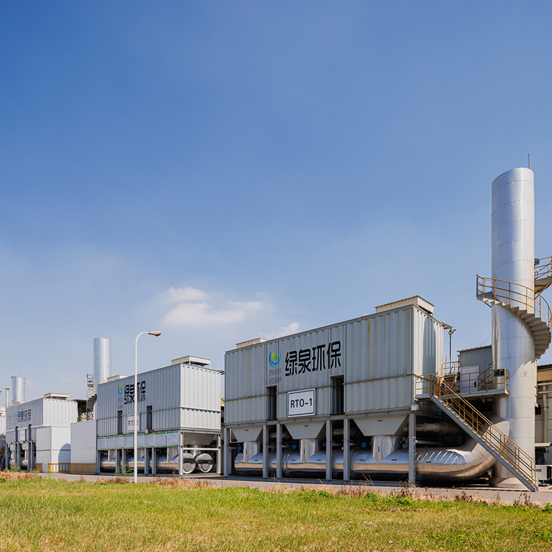
Overview Of Tower-Type RTO Regenerative Thermal Oxidizer (RTO) is an organic waste gas treatment equipment that combines high-temperature oxidation wi...
See Details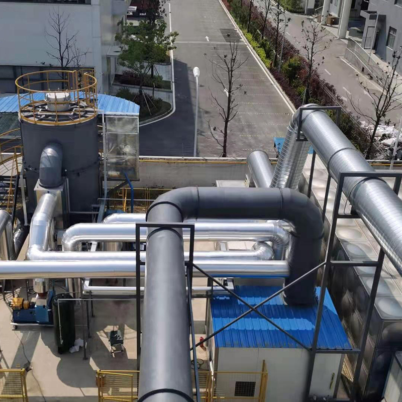
Overview Of Tower-Type RTO Our company offers two types of rotary RTO, which are the rotary RTO and the single barrel multi-valve RTO. The rotary RTO,...
See Details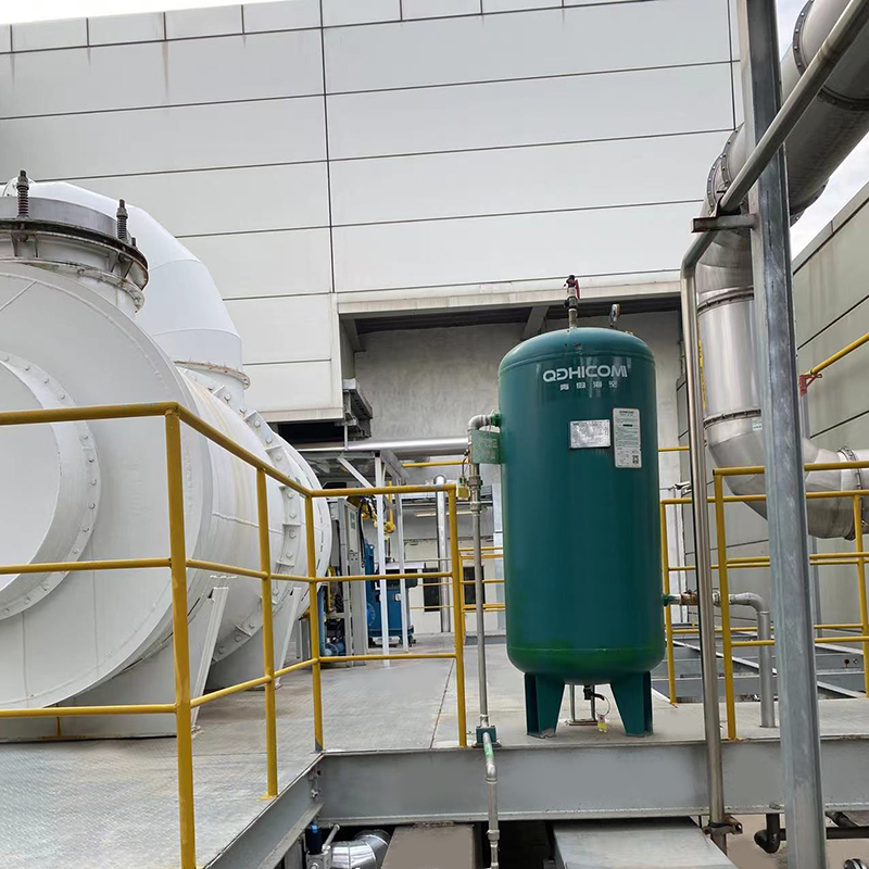
Overview Direct combustion high-temperature incineration equipment, abbreviated as TO, utilizes the heat generated by the combustion of auxiliary fuel...
See Details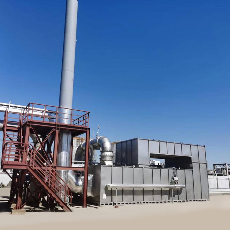
Overview Catalytic combustion is a purification method that uses catalysts to oxidize and decompose combustible substances in exhaust gas at low tempe...
See Details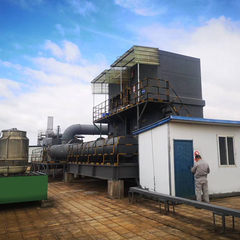
Overview Thermal storage catalytic oxidation (Regenerative Catalytic Oxidizer/RCO) is an organic waste gas treatment equipment that combines low-tempe...
See Details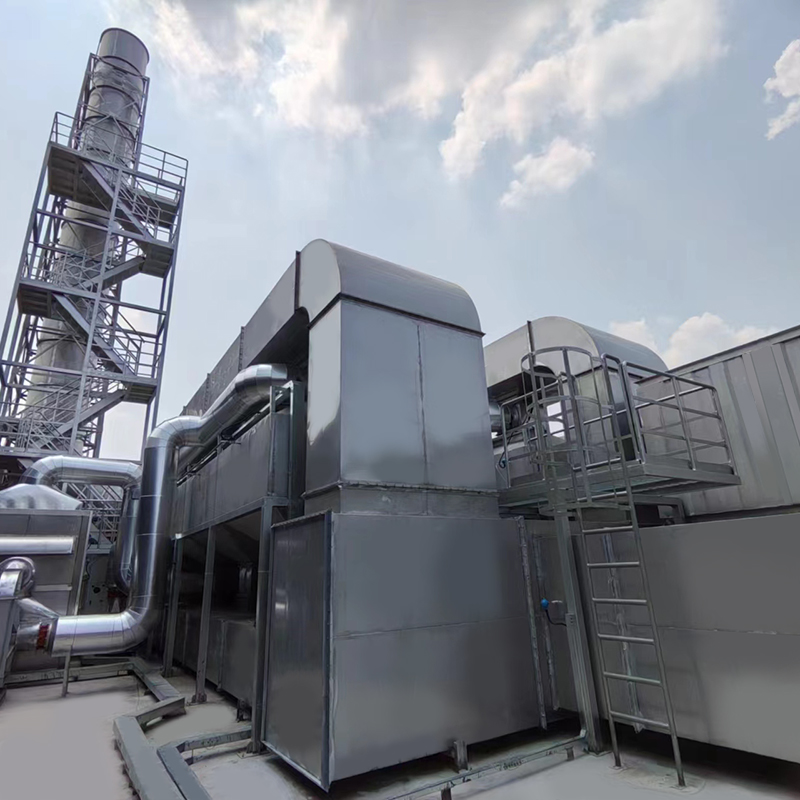
Overview of Activated Carbon Fiber Organic Solvent Purification Recovery Device The Activated Carbon Fiber Organic Solvent Purification Recovery Syste...
See Details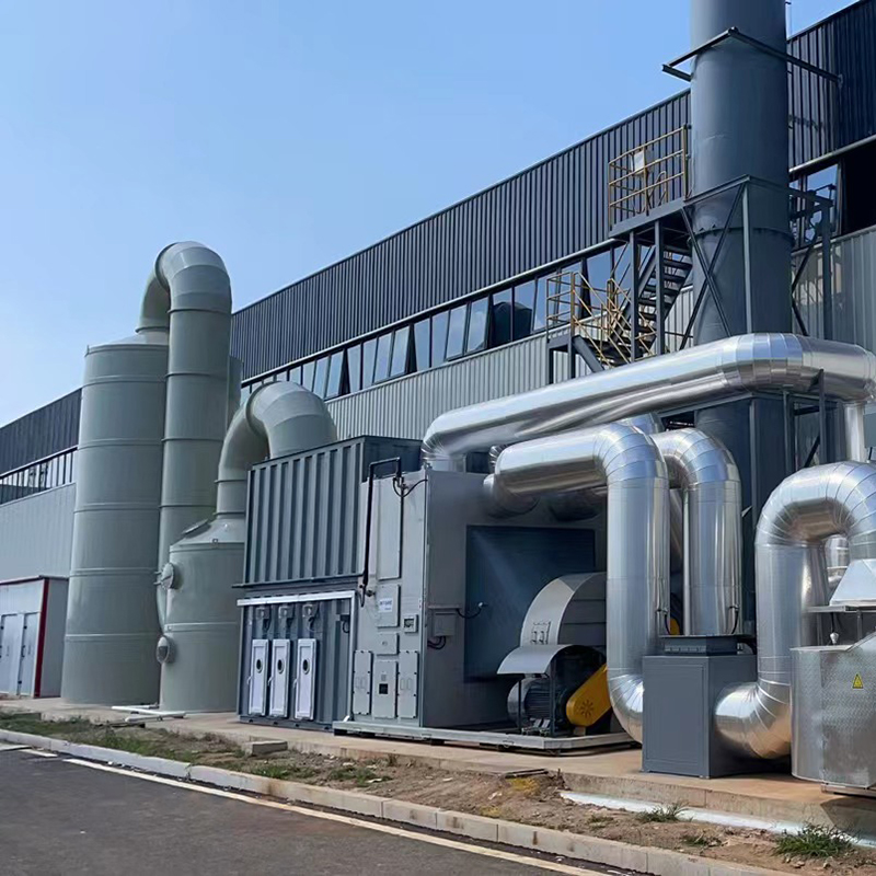
Concept Of Fixed Bed Zeolite + Catalytic Combustion As A Set Of Equipment The fixed bed zeolite + catalytic combustion device is suitable for the conc...
See Details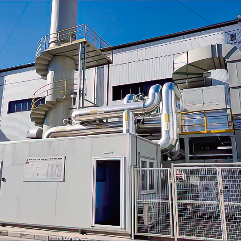
Concept Of Zeolite Rotary Wheel + Catalytic Combustion As A Set Of Equipment In the combined process of organic waste gas and waste gas treatment, the...
See Details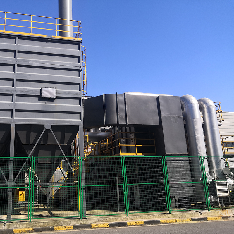
The Concept Of Zeolite Wheel+ Direct Combustion High-Temperature Incineration Equipment The purpose of employing rotary drum zeolite adsorption for or...
See Details
Overview Solid waste incineration furnaces are essential equipment in the management of solid waste, designed to transform waste materials into ash an...
See DetailsMOBILE
Product Manual

Copyright © Lv quan Environmental Protection Engineering Technology Co., Ltd. All Rights Reserved. Vocs Organic Waste Gas Treatment Engineering Equipment Manufacturer

